File list
This special page shows all uploaded files. When filtered by user, only files where that user uploaded the most recent version of the file are shown.
| Date | Thumbnail | Size | User | Description | Versions | |
|---|---|---|---|---|---|---|
| 13:51, 30 November 2020 | DioIsolated12V.gif (file) |  | 2 KB | JL | 1 | |
| 13:50, 30 November 2020 | DioIsolated5V.gif (file) |  | 1 KB | JL | 1 | |
| 13:51, 30 November 2020 | DioLed.gif (file) |  | 1 KB | JL | 1 | |
| 13:51, 30 November 2020 | DioOptoIsolator.gif (file) |  | 2 KB | JL | 1 | |
| 13:52, 30 November 2020 | DioSsr.gif (file) |  | 2 KB | JL | 1 | |
| 13:52, 30 November 2020 | DioSwitch.gif (file) |  | 966 B | JL | 1 | |
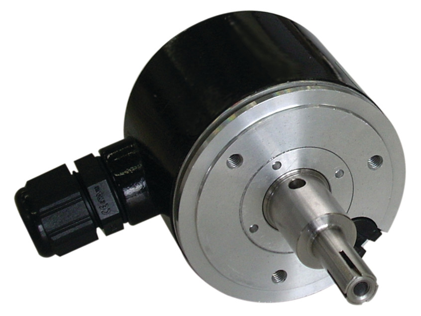
| 09:13, 18 April 2017 | IncrementalEncoder.jpg (file) |  | 80 KB | JL | (An incremental encoder. This image was derived from Wikimedia Commons file Encoder_incremental Dynapar_B58N.jpg and is licensed under Creative Commons Attribution 4.0 International.) | 1 |
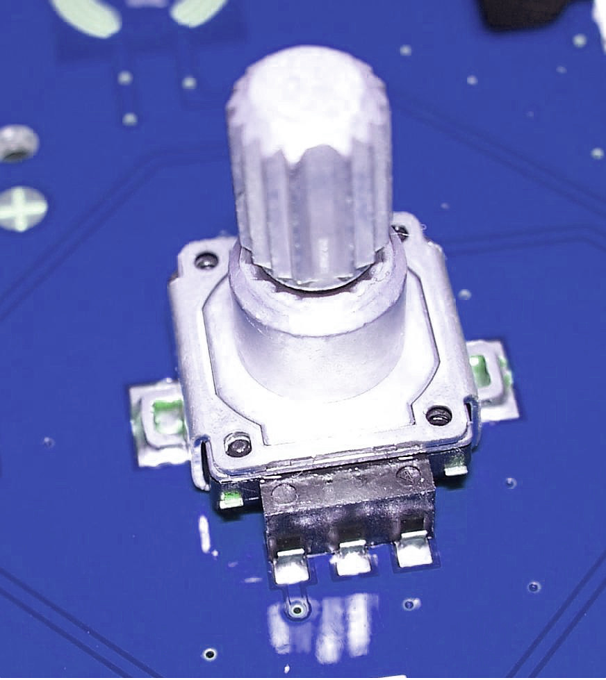
| 09:40, 18 April 2017 | PanelMountEncoder.jpg (file) |  | 113 KB | JL | (A panel mount incremental encoder with integrated pushbutton. This image was derived from Wikimedia Commons file Rot_enc.JPG and is licensed under Creative Commons Attribution-Share Alike 3.0 Unported.) | 1 |
| 13:02, 1 September 2016 | SmartAD pinout.gif (file) |  | 39 KB | JL | (Connector pinout used by Sensoray Smart A/D boards (e.g., model 418, 419, 518, 618, 619). For each sensor channel x (in range 0:7), PHx/PLx supply excitation to a passive sensor (if needed) and SHx/SLx are the differential analog inputs. TREF and +12V ...) | 1 |
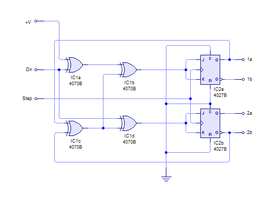
| 11:44, 26 April 2017 | StepperMotorDriver.png (file) |  | 4 KB | JL | (The input section of a simple stepper motor driver.) | 1 |
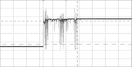
| 10:16, 18 April 2017 | SwitchBounce.png (file) |  | 5 KB | JL | (Switch contact bounce viewed on an oscilloscope. ) | 1 |
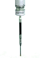
| 08:36, 18 April 2017 | TouchProbe.jpg (file) |  | 4 KB | JL | (A touch-trigger probe) | 1 |
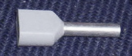
| 12:26, 7 March 2022 | Twin wire ferrule.jpg (file) |  | 11 KB | JL | (Twin wire ferrule.) | 1 |
| 15:55, 27 September 2017 | Vfd wiring no1.gif (file) |  | 9 KB | JL | (Don't do this! It creates a ground loop that may cause a DC offset voltage and/or couple noise onto the VFD's voltage input.) | 1 |
| 15:58, 27 September 2017 | Vfd wiring no2.gif (file) |  | 9 KB | JL | (Don't do this! It won't create a ground loop, but it may cause a DC offset voltage at the VFD voltage input because the 826 GND signal is probably not the same voltage as the VFD analog common (chassis ground).) | 1 |
| 16:00, 27 September 2017 | Vfd wiring yes.gif (file) |  | 7 KB | JL | (This is the correct way to connect a DAC to a VFD. Note that a dedicated conductor is used for the analog ground. This effectively makes the connection a differential pair, and completely avoids ground loop problems.) | 1 |
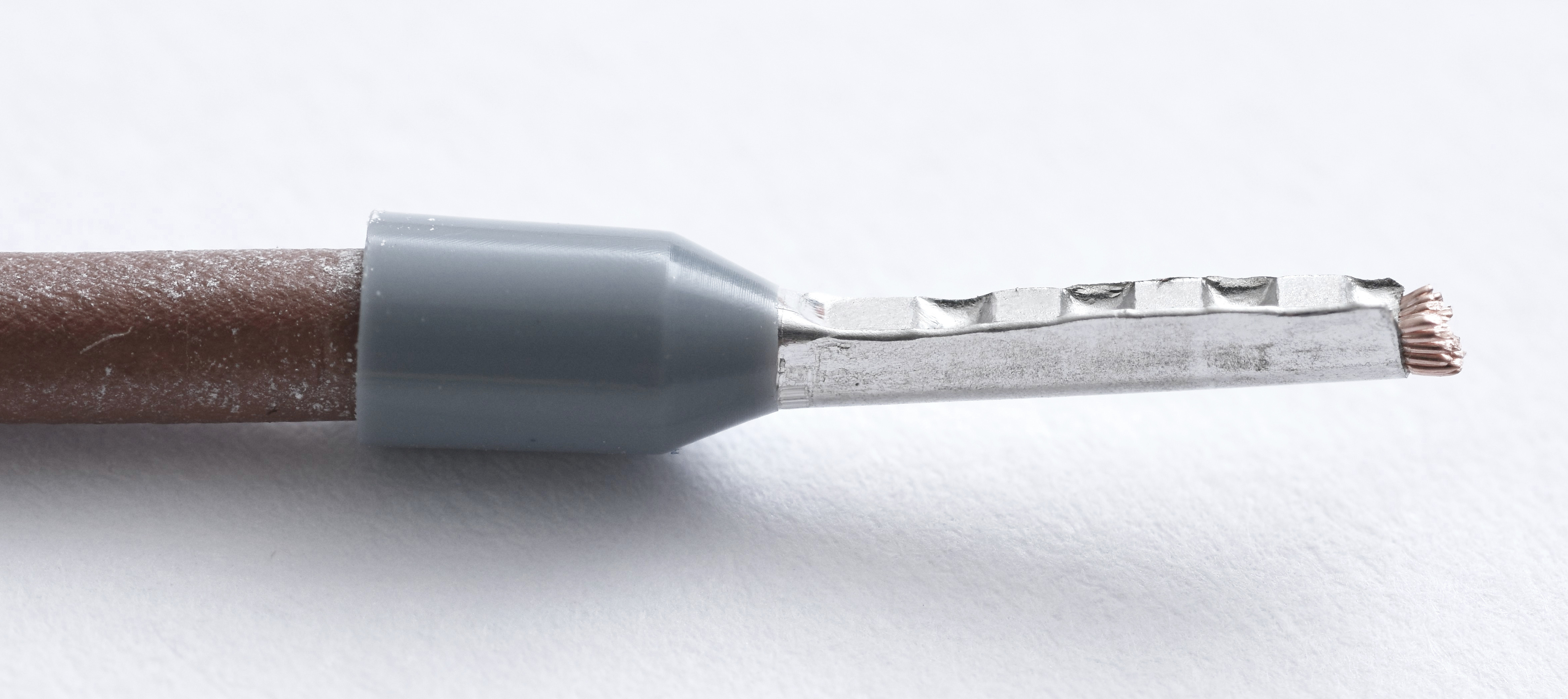
| 13:16, 4 March 2022 | Wire ferrule.jpg (file) |  | 884 KB | JL | (Wire ferrule crimped onto a stranded conductor.) | 1 |
First page |
 Previous page |
Next page |
Last page |