File list
This special page shows all uploaded files. When filtered by user, only files where that user uploaded the most recent version of the file are shown.
| Date | Thumbnail | Size | User | Description | Versions | |
|---|---|---|---|---|---|---|
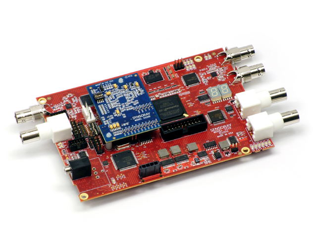
| 16:31, 4 April 2014 | 2226 photo.jpg (file) |  | 190 KB | JL | (Sensoray Model 2226) | 1 |
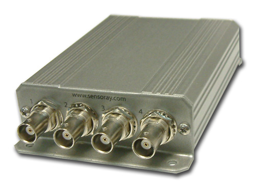
| 16:56, 4 April 2014 | 2255 photo.jpg (file) |  | 68 KB | JL | (Model 2255) | 1 |
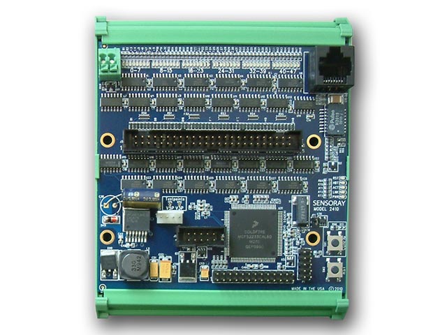
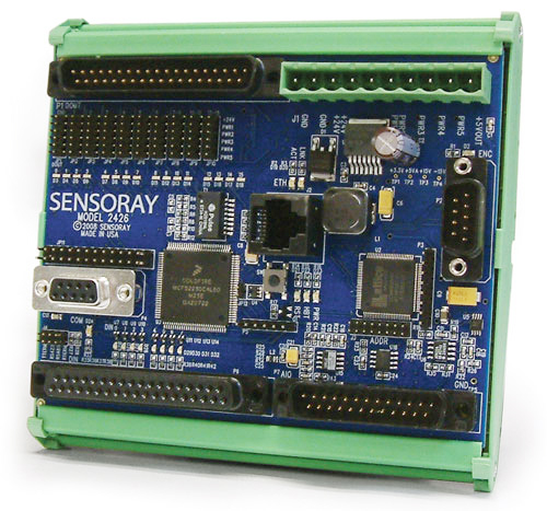
| 10:32, 26 May 2016 | 2410.jpg (file) |  | 81 KB | JL | (Model 2410 is a compact open-frame module that interfaces 48 general-purpose TTL/CMOS compatible digital input/output (DIO) signals to Ethernet.) | 1 |
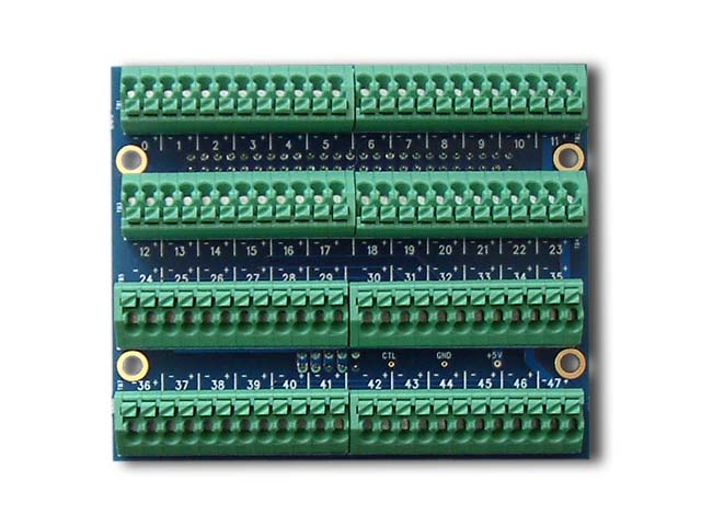
| 15:46, 11 December 2017 | 2410TA photo.jpg (file) |  | 67 KB | JL | (Model 2410TA termination board, which can be top-mounted to a 2410 module to add convenient field wiring terminal blocks. The spring-loaded terminals allow quick connection of 24-16 gauge wires.) | 1 |
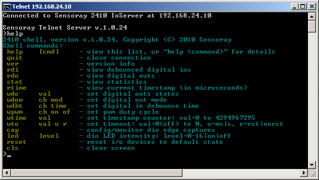
| 16:05, 7 August 2017 | 2410 telnet help.png (file) |  | 13 KB | JL | (2410 telnet command overview. To see this info, open a telnet session on the 2410 and type 'help'. To see more detailed info about a command, type 'help <command>' (e.g., 'help wdo').) | 1 |
| 14:31, 2 March 2020 | 2426 photo.jpg (file) |  | 203 KB | JL | 1 | |
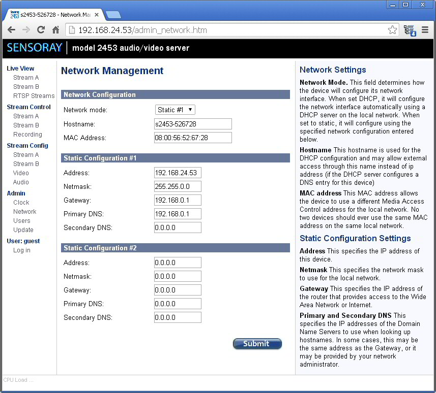
| 12:29, 6 December 2016 | 2453AdminNet.jpg (file) |  | 175 KB | JM | (2453 network admin page from the manual) | 1 |
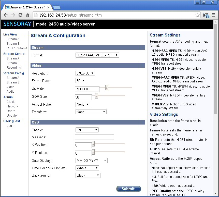
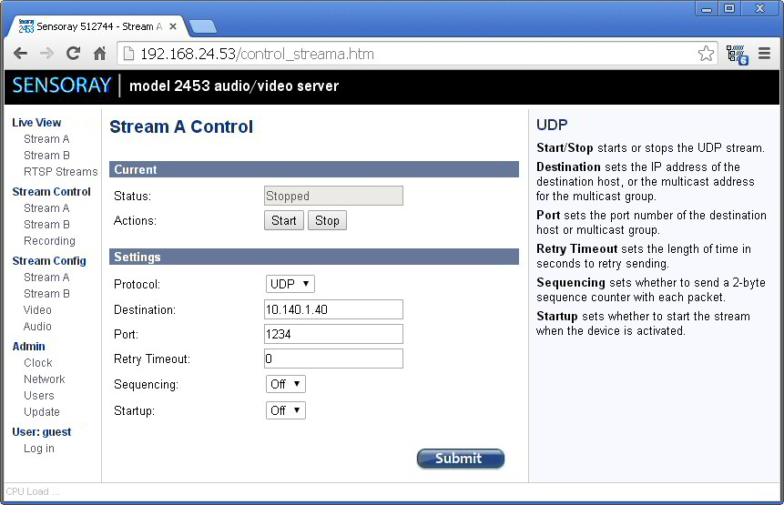
| 12:28, 6 December 2016 | 2453configA.jpg (file) |  | 155 KB | JM | (2453 configure stream A from the manual) | 1 |
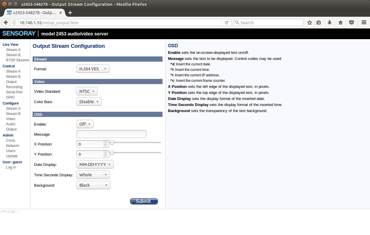
| 13:05, 6 December 2016 | 2453configOut.png (file) |  | 146 KB | JM | (2453 output config page created using fw 1270) | 1 |
| 12:29, 6 December 2016 | 2453controlA.jpg (file) |  | 101 KB | JM | (2453 control stream A from the manual) | 1 |
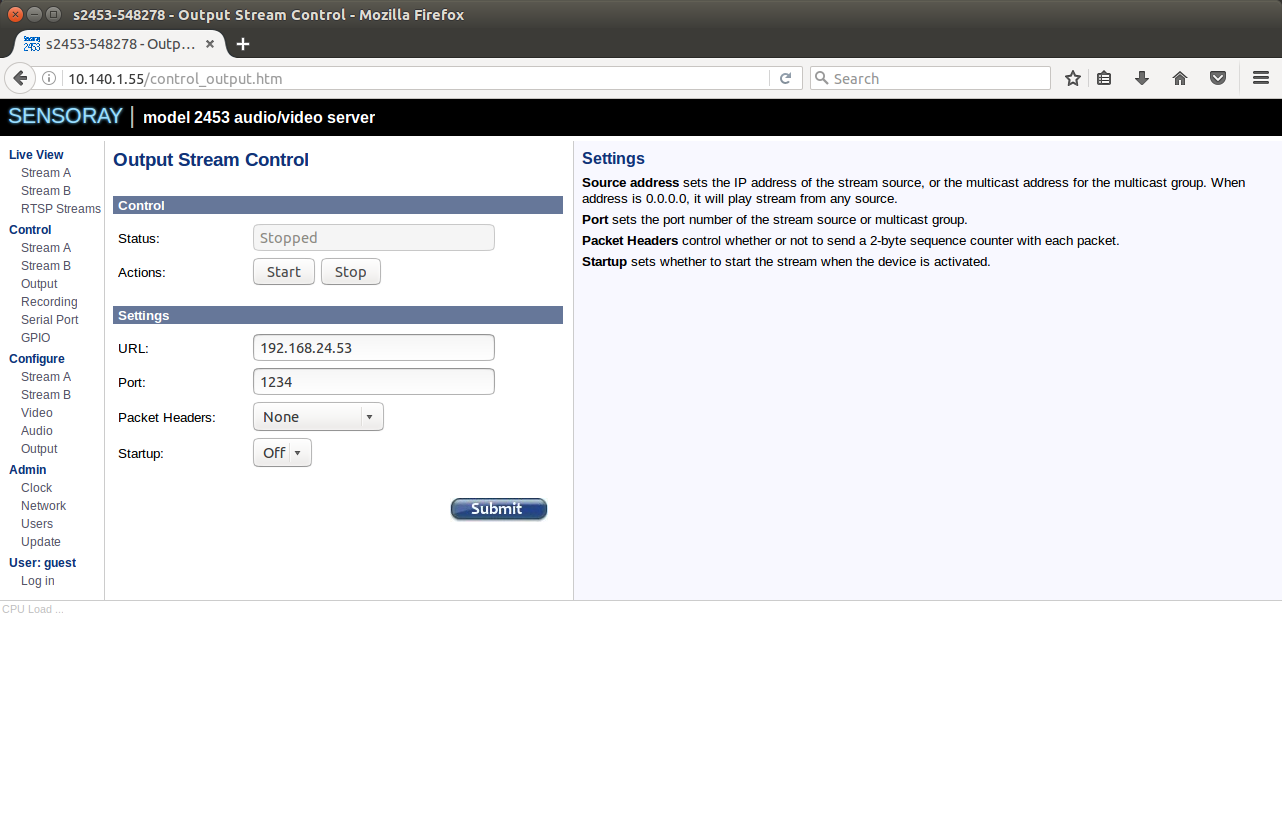
| 13:06, 6 December 2016 | 2453controlOut.png (file) |  | 113 KB | JM | (2453 output control page taken using fw 1270) | 1 |
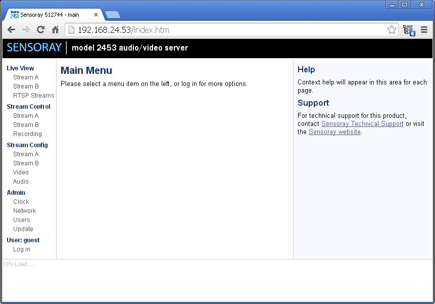
| 12:27, 6 December 2016 | 2453index.jpg (file) |  | 67 KB | JM | (2453 index.htm from the manual) | 1 |
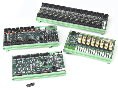
| 15:04, 3 January 2018 | 2600 photo.jpg (file) |  | 169 KB | JL | (2600 system modules) | 1 |
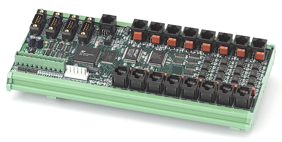
| 15:05, 3 January 2018 | 2601 photo.jpg (file) |  | 138 KB | JL | (2601 module) | 1 |
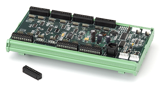
| 15:06, 3 January 2018 | 2608 photo.jpg (file) |  | 131 KB | JL | (2608 module) | 1 |
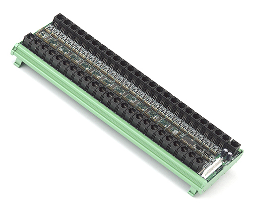
| 17:38, 20 February 2019 | 2610 photo.jpg (file) |  | 129 KB | JL | (Sensoray model 2610 48-channel digital I/O) | 2 |
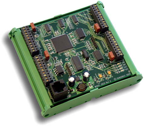
| 15:07, 3 January 2018 | 2620 photo.jpg (file) |  | 171 KB | JL | (2620 module) | 1 |
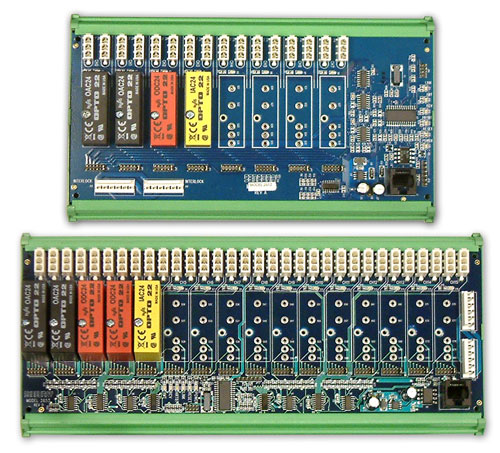
| 15:07, 3 January 2018 | 2652 53 photo.jpg (file) |  | 93 KB | JL | (2652/2653 modules) | 1 |
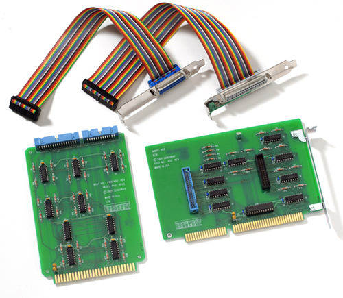
| 13:51, 8 August 2018 | 422 photo.jpg (file) |  | 191 KB | JL | (Model 422) | 1 |
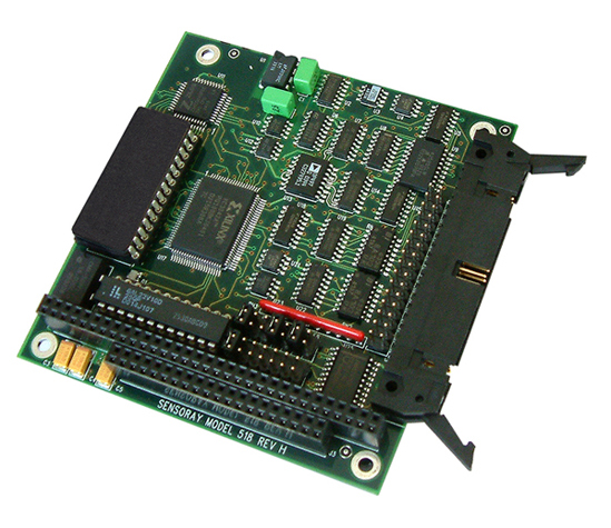
| 16:47, 29 March 2017 | 518 photo.jpg (file) |  | 246 KB | JL | (Reverted to version as of 17:48, 11 March 2016) | 3 |
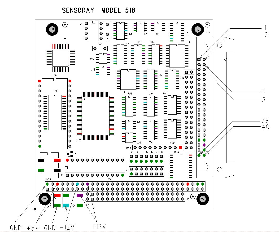
| 12:39, 21 March 2016 | 518 power.jpg (file) |  | 171 KB | JL | (Power supply test points on model 518.) | 1 |
| 14:17, 17 June 2020 | 7409TB CCJ.gif (file) |  | 8 KB | JL | (Thermocouple reference junction sensor used on 7409TB termination board.) | 1 |
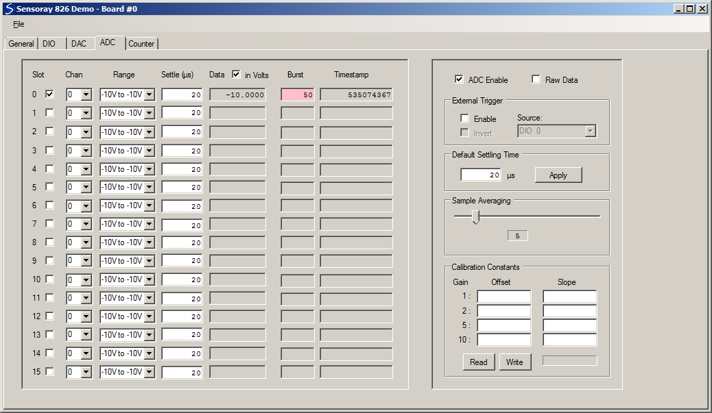
| 11:30, 17 May 2017 | 826DemoAdc.png (file) |  | 40 KB | JL | (826 VB.NET demo screenshot, ADC tab) | 1 |
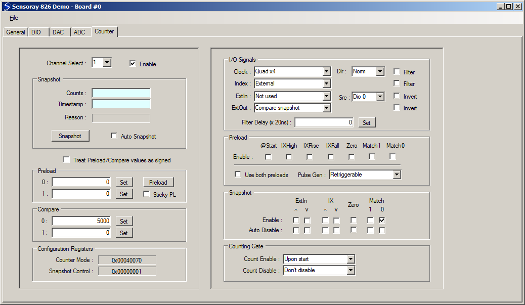
| 15:09, 16 May 2017 | 826DemoCounter1.png (file) |  | 41 KB | JL | (Screenshot, 826 VB.NET demo program, showing counter1 configured as 1-shot) | 1 |
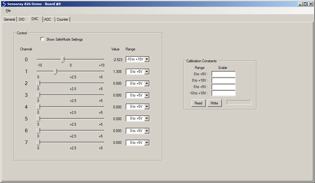
| 11:29, 17 May 2017 | 826DemoDac.png (file) |  | 30 KB | JL | (826 VB.NET demo screenshot, DAC tab) | 1 |
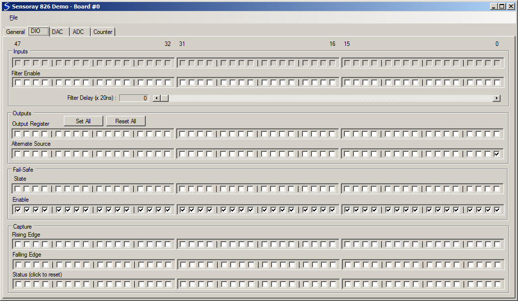
| 15:11, 16 May 2017 | 826DemoDio.png (file) |  | 23 KB | JL | (Screenshot, 826 VB.NET demo program, showing dio0 configured as counter0 output.) | 1 |
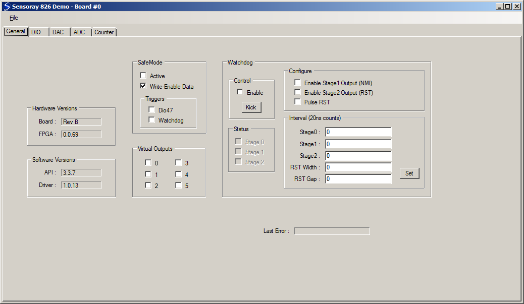
| 15:12, 16 May 2017 | 826DemoGeneral.png (file) |  | 33 KB | JL | (Screenshot, 826 VB.NET demo program, General tab, showing Write-enable Data checked.) | 1 |
| 10:51, 11 May 2016 | 826PwmWatchdog.gif (file) |  | 27 KB | JL | (show inverted DIO output; label DIO_out router) | 2 |
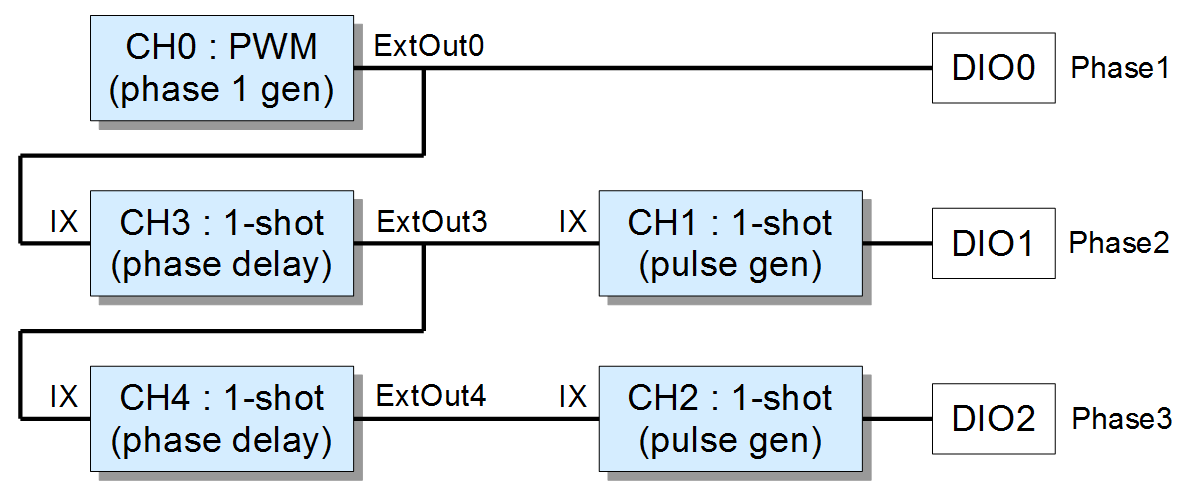
| 08:31, 1 March 2017 | 826 3Phase pwm.png (file) |  | 32 KB | JL | (fixed dio/counter routability) | 3 |
| 16:00, 25 February 2021 | 826 adcval.gif (file) | 4 KB | JL | (Format of 32-bit sample from 826 ADC.) | 1 | |
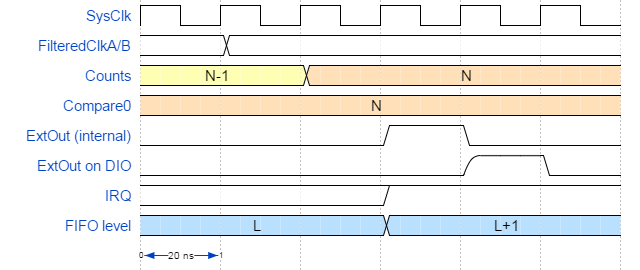
| 11:51, 4 August 2016 | 826 counter timing.png (file) |  | 21 KB | JL | 2 | |
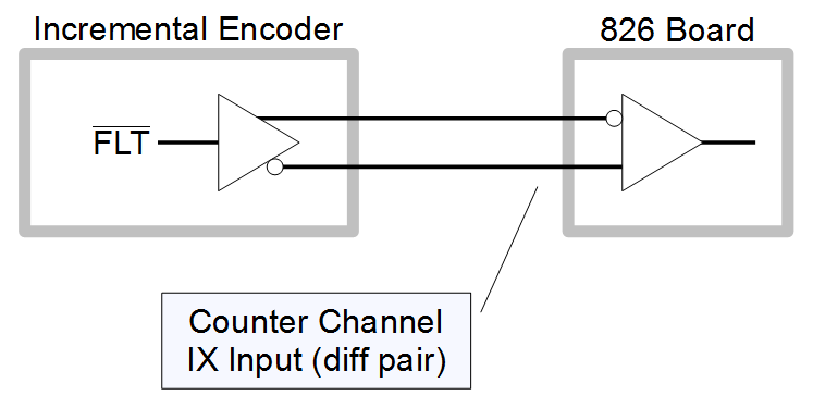
| 13:15, 4 November 2016 | 826 encoder FLT.png (file) |  | 13 KB | JL | (Using an 826 counter channel to monitor an incremental encoder's active-low FAULT output. The differential pair is swapped between line driver and receiver so that a disconnected or unpowered encoder will be recognized as a fault.) | 1 |
| 10:49, 22 February 2017 | 826 estop.gif (file) |  | 7 KB | JL | (A robust way to connect a 24VDC emergency-stop contact to model 826.) | 1 |
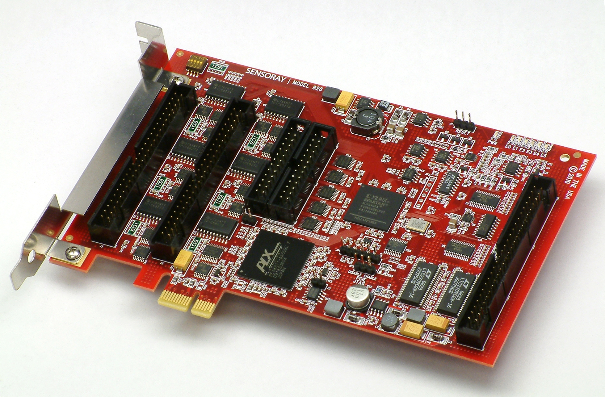
| 16:41, 4 April 2014 | 826 photo.jpg (file) |  | 1.81 MB | JL | (Sensoray model 826 board) | 1 |
| 12:18, 11 August 2017 | 826 pinout J1.gif (file) |  | 31 KB | JL | 1 | |
| 12:18, 11 August 2017 | 826 pinout J2.gif (file) |  | 30 KB | JL | 1 | |
| 12:19, 11 August 2017 | 826 pinout J3.gif (file) |  | 30 KB | JL | 1 | |
| 12:19, 11 August 2017 | 826 pinout J4.gif (file) |  | 14 KB | JL | 1 | |
| 12:19, 11 August 2017 | 826 pinout J5.gif (file) |  | 15 KB | JL | 1 | |
| 13:49, 27 July 2018 | 826 pinout P2.gif (file) |  | 4 KB | JL | (Pinout of connector P2 on model 826) | 1 |
| 17:42, 28 February 2017 | 826 quadrature gen.gif (file) | 16 KB | JL | (corrected dio/counter matching) | 2 | |
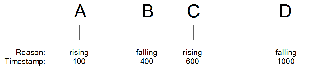
| 07:33, 9 June 2016 | 826 serial data capture.png (file) | 7 KB | JL | (Using an 826 counter channel to capture data from a serial data source. Each data edge causes a counter snapshot that contains a reason code and timestamp.) | 1 | |
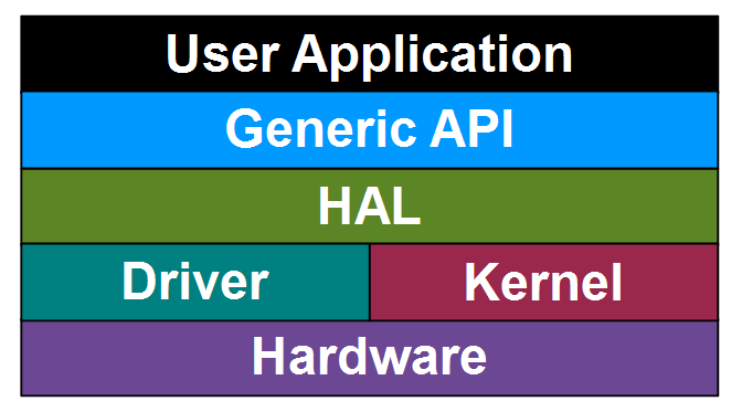
| 09:52, 22 May 2017 | 826 software stack.png (file) |  | 13 KB | JL | (Simplified 826 software stack) | 1 |
| 09:18, 9 November 2016 | 826 ttl encoder.gif (file) |  | 27 KB | JL | (Wiring diagram showing how to connect two TTL/CMOS-compatible single-ended incremental encoders to the 826 board using counter channels 0 and 1.) | 1 |
| 12:06, 12 January 2021 | 826 vs 626 pinouts.gif (file) |  | 49 KB | JL | (Pinout differences, analog I/O connector, model 826 vs. model 626) | 1 |
| 16:09, 25 April 2013 | AdgGroundReference.gif (file) |  | 8 KB | JL | (cropped) | 2 |
| 10:25, 2 December 2020 | AinBattery.gif (file) |  | 1 KB | JL | 1 | |
| 10:26, 2 December 2020 | AinLM35.gif (file) |  | 2 KB | JL | 1 | |
| 10:26, 2 December 2020 | AinPot.gif (file) |  | 1 KB | JL | 1 | |
| 13:26, 2 December 2020 | AinPrecisionThermistor.gif (file) |  | 4 KB | JL | 2 |
First page |
Previous page |
 Next page |
Last page |