Uploads by JL
Jump to navigation
Jump to search
This special page shows all uploaded files.
| Date | Name | Thumbnail | Size | Description | Versions |
|---|---|---|---|---|---|
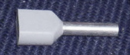
| 12:26, 7 March 2022 | Twin wire ferrule.jpg (file) |  |
11 KB | Twin wire ferrule. | 1 |
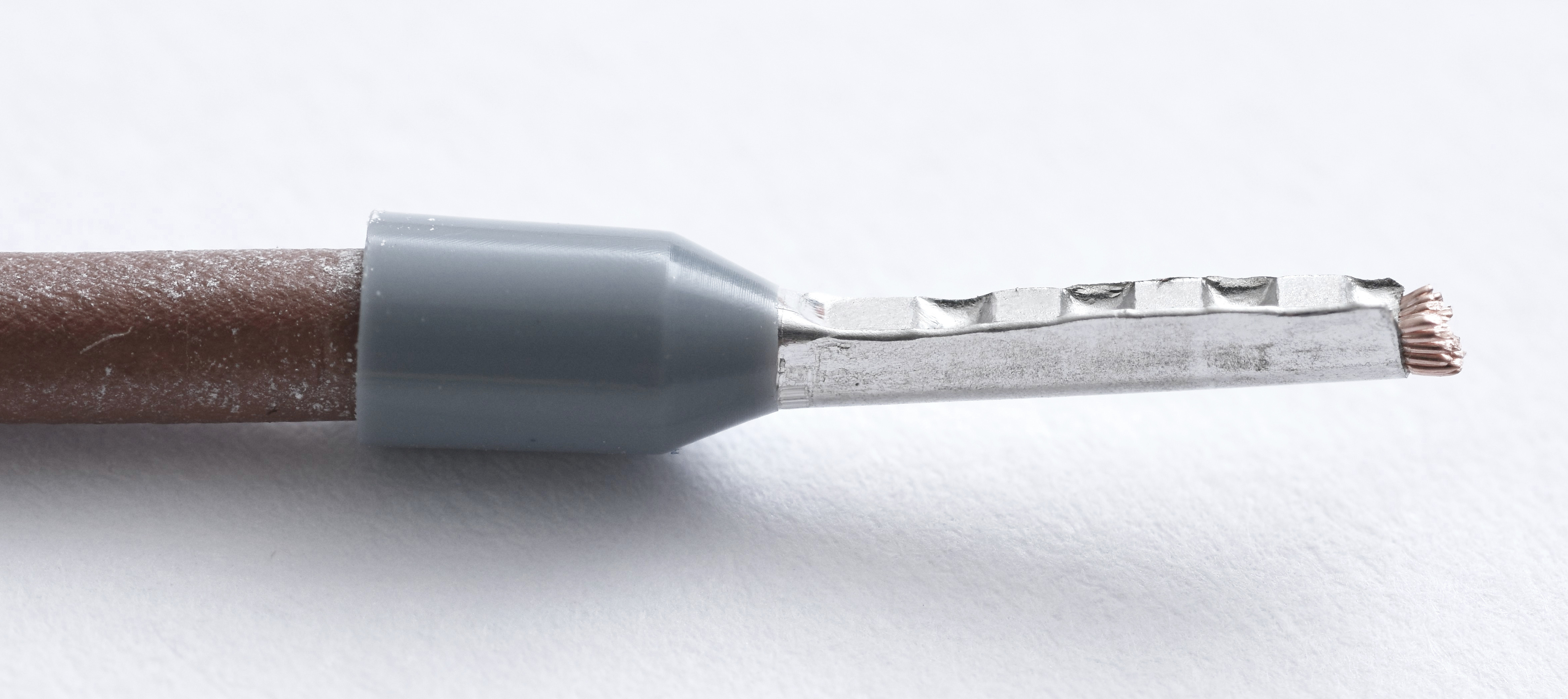
| 13:16, 4 March 2022 | Wire ferrule.jpg (file) |  |
884 KB | Wire ferrule crimped onto a stranded conductor. | 1 |
| 16:00, 25 February 2021 | 826 adcval.gif (file) | 4 KB | Format of 32-bit sample from 826 ADC. | 1 | |
| 12:06, 12 January 2021 | 826 vs 626 pinouts.gif (file) |  |
49 KB | Pinout differences, analog I/O connector, model 826 vs. model 626 | 1 |
| 13:26, 2 December 2020 | AinPrecisionThermistor.gif (file) |  |
4 KB | 2 | |
| 10:27, 2 December 2020 | AinSensorIsolated.gif (file) |  |
3 KB | 1 | |
| 10:27, 2 December 2020 | AinSensorGalvanic.gif (file) |  |
3 KB | 1 | |
| 10:26, 2 December 2020 | AinPot.gif (file) |  |
1 KB | 1 | |
| 10:26, 2 December 2020 | AinLM35.gif (file) |  |
2 KB | 1 | |
| 10:25, 2 December 2020 | AinBattery.gif (file) |  |
1 KB | 1 | |
| 13:52, 30 November 2020 | DioSwitch.gif (file) |  |
966 bytes | 1 | |
| 13:52, 30 November 2020 | DioSsr.gif (file) |  |
2 KB | 1 | |
| 13:51, 30 November 2020 | DioOptoIsolator.gif (file) |  |
2 KB | 1 | |
| 13:51, 30 November 2020 | DioLed.gif (file) |  |
1 KB | 1 | |
| 13:51, 30 November 2020 | DioIsolated12V.gif (file) |  |
2 KB | 1 | |
| 13:50, 30 November 2020 | DioIsolated5V.gif (file) |  |
1 KB | 1 | |
| 14:17, 17 June 2020 | 7409TB CCJ.gif (file) |  |
8 KB | Thermocouple reference junction sensor used on 7409TB termination board. | 1 |
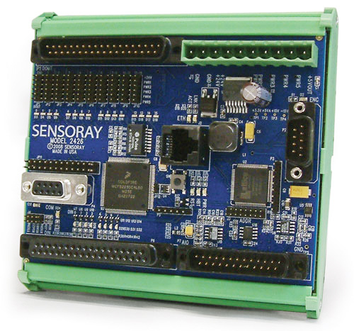
| 14:31, 2 March 2020 | 2426 photo.jpg (file) |  |
203 KB | 1 | |
| 09:43, 28 February 2020 | Design assistant.gif (file) |  |
2 KB | 2600 Design Assistant icon | 1 |
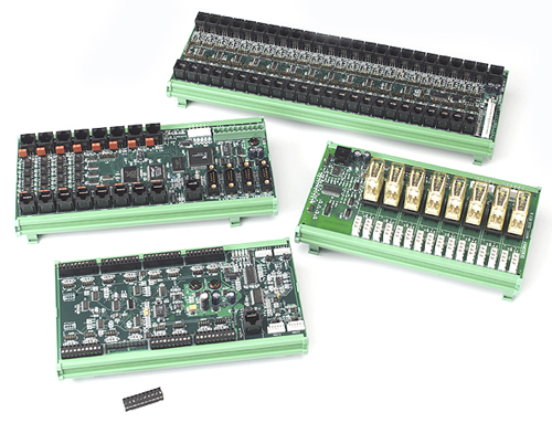
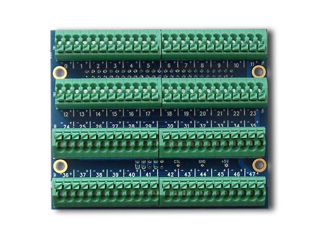
| 17:38, 20 February 2019 | 2610 photo.jpg (file) |  |
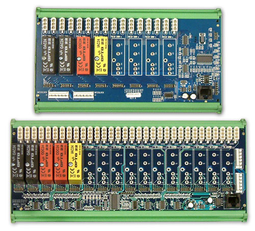
129 KB | Sensoray model 2610 48-channel digital I/O | 2 |
| 13:51, 8 August 2018 | 422 photo.jpg (file) |  |
191 KB | Model 422 | 1 |
| 13:49, 27 July 2018 | 826 pinout P2.gif (file) |  |
4 KB | Pinout of connector P2 on model 826 | 1 |
| 15:07, 3 January 2018 | 2652 53 photo.jpg (file) |  |
93 KB | 2652/2653 modules | 1 |
| 15:07, 3 January 2018 | 2620 photo.jpg (file) |  |
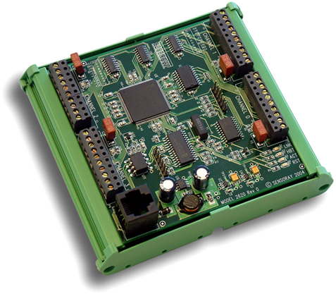
171 KB | 2620 module | 1 |
| 15:06, 3 January 2018 | 2608 photo.jpg (file) |  |
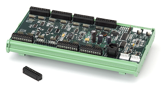
131 KB | 2608 module | 1 |
| 15:05, 3 January 2018 | 2601 photo.jpg (file) |  |
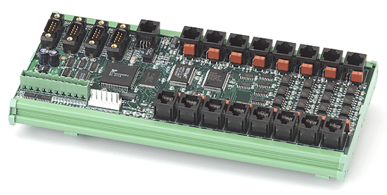
138 KB | 2601 module | 1 |
| 15:04, 3 January 2018 | 2600 photo.jpg (file) |  |
169 KB | 2600 system modules | 1 |
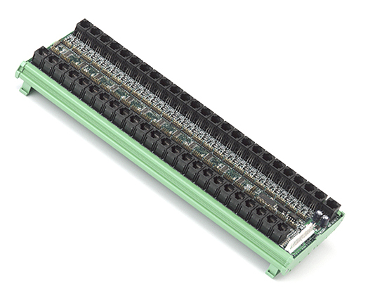
| 15:46, 11 December 2017 | 2410TA photo.jpg (file) |  |
67 KB | Model 2410TA termination board, which can be top-mounted to a 2410 module to add convenient field wiring terminal blocks. The spring-loaded terminals allow quick connection of 24-16 gauge wires. | 1 |
| 16:00, 27 September 2017 | Vfd wiring yes.gif (file) |  |
7 KB | This is the correct way to connect a DAC to a VFD. Note that a dedicated conductor is used for the analog ground. This effectively makes the connection a differential pair, and completely avoids ground loop problems. | 1 |
| 15:58, 27 September 2017 | Vfd wiring no2.gif (file) |  |
9 KB | Don't do this! It won't create a ground loop, but it may cause a DC offset voltage at the VFD voltage input because the 826 GND signal is probably not the same voltage as the VFD analog common (chassis ground). | 1 |
| 15:55, 27 September 2017 | Vfd wiring no1.gif (file) |  |
9 KB | Don't do this! It creates a ground loop that may cause a DC offset voltage and/or couple noise onto the VFD's voltage input. | 1 |
| 12:19, 11 August 2017 | 826 pinout J5.gif (file) |  |
15 KB | 1 | |
| 12:19, 11 August 2017 | 826 pinout J4.gif (file) |  |
14 KB | 1 | |
| 12:19, 11 August 2017 | 826 pinout J3.gif (file) |  |
30 KB | 1 | |
| 12:18, 11 August 2017 | 826 pinout J2.gif (file) |  |
30 KB | 1 | |
| 12:18, 11 August 2017 | 826 pinout J1.gif (file) |  |
31 KB | 1 | |
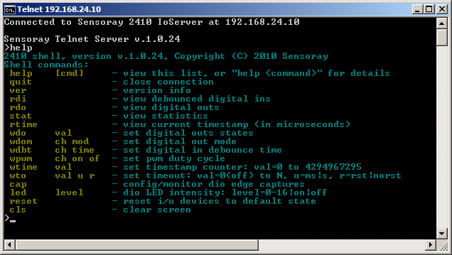
| 16:05, 7 August 2017 | 2410 telnet help.png (file) |  |
13 KB | 2410 telnet command overview. To see this info, open a telnet session on the 2410 and type 'help'. To see more detailed info about a command, type 'help <command>' (e.g., 'help wdo'). | 1 |
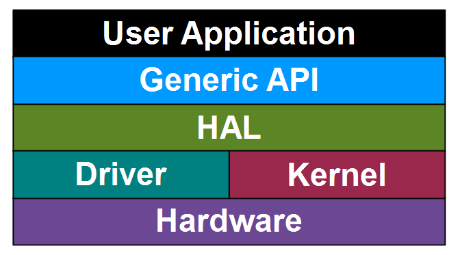
| 09:52, 22 May 2017 | 826 software stack.png (file) |  |
13 KB | Simplified 826 software stack | 1 |
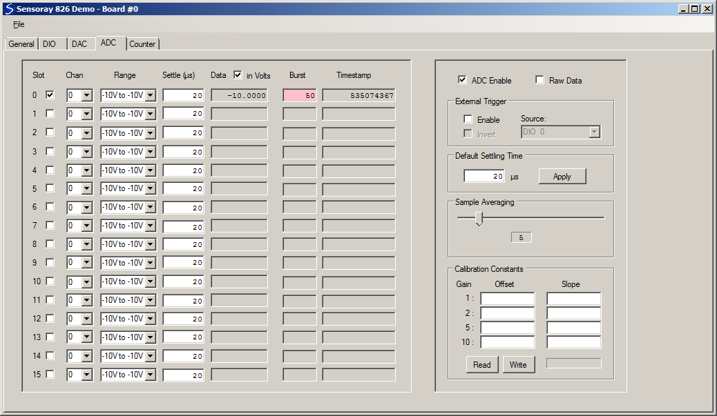
| 11:30, 17 May 2017 | 826DemoAdc.png (file) |  |
40 KB | 826 VB.NET demo screenshot, ADC tab | 1 |
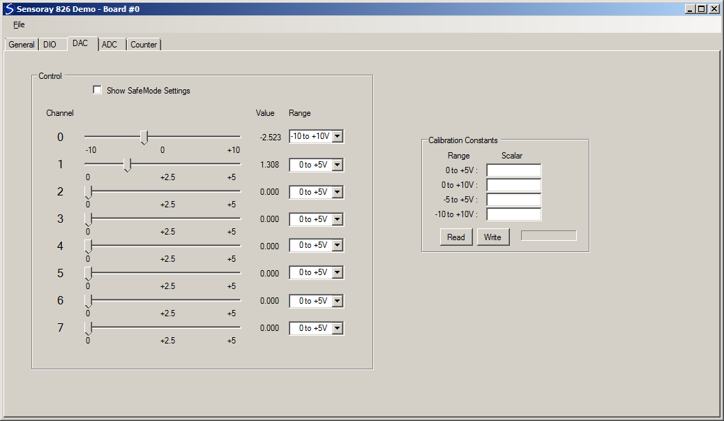
| 11:29, 17 May 2017 | 826DemoDac.png (file) |  |
30 KB | 826 VB.NET demo screenshot, DAC tab | 1 |
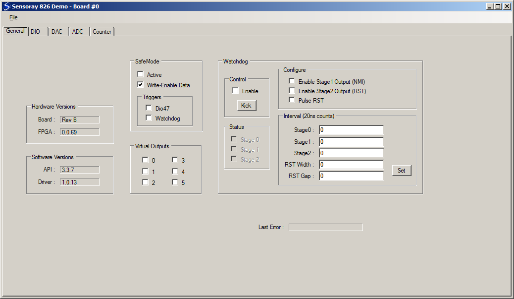
| 15:12, 16 May 2017 | 826DemoGeneral.png (file) |  |
33 KB | Screenshot, 826 VB.NET demo program, General tab, showing Write-enable Data checked. | 1 |
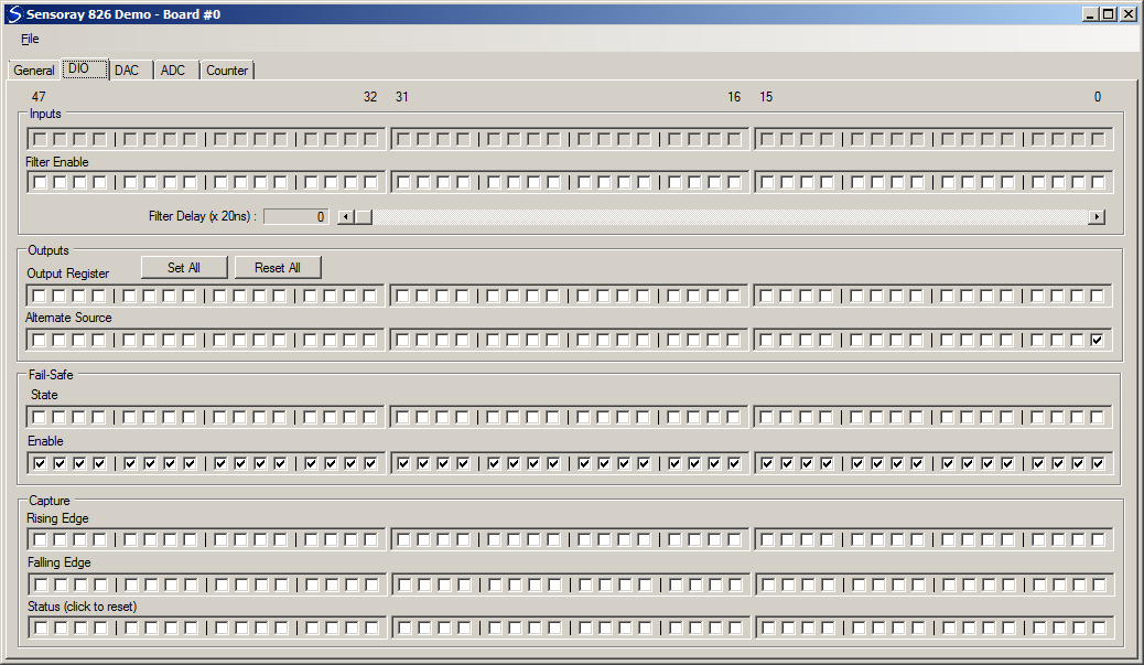
| 15:11, 16 May 2017 | 826DemoDio.png (file) |  |
23 KB | Screenshot, 826 VB.NET demo program, showing dio0 configured as counter0 output. | 1 |
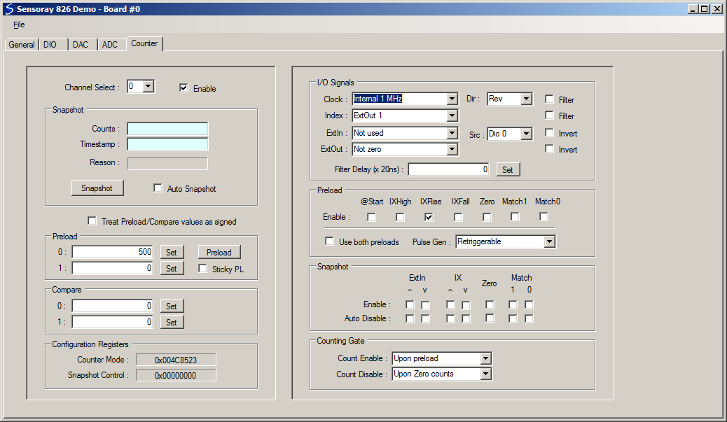
| 15:10, 16 May 2017 | Counter0.png (file) |  |
42 KB | Screenshot, 826 VB.NET demo program, showing counter0 configured as encoder interface. | 1 |
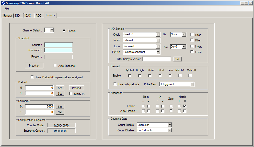
| 15:09, 16 May 2017 | 826DemoCounter1.png (file) |  |
41 KB | Screenshot, 826 VB.NET demo program, showing counter1 configured as 1-shot | 1 |
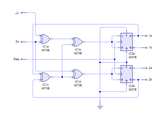
| 11:44, 26 April 2017 | StepperMotorDriver.png (file) |  |
4 KB | The input section of a simple stepper motor driver. | 1 |
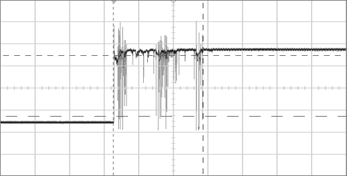
| 10:16, 18 April 2017 | SwitchBounce.png (file) |  |
5 KB | Switch contact bounce viewed on an oscilloscope. | 1 |
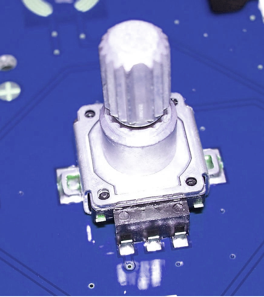
| 09:40, 18 April 2017 | PanelMountEncoder.jpg (file) |  |
113 KB | A panel mount incremental encoder with integrated pushbutton. This image was derived from Wikimedia Commons file Rot_enc.JPG and is licensed under Creative Commons Attribution-Share Alike 3.0 Unported. | 1 |
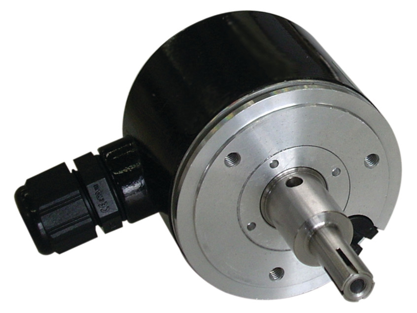
| 09:13, 18 April 2017 | IncrementalEncoder.jpg (file) |  |
80 KB | An incremental encoder. This image was derived from Wikimedia Commons file Encoder_incremental Dynapar_B58N.jpg and is licensed under Creative Commons Attribution 4.0 International. | 1 |
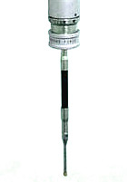
| 08:36, 18 April 2017 | TouchProbe.jpg (file) |  |
4 KB | A touch-trigger probe | 1 |
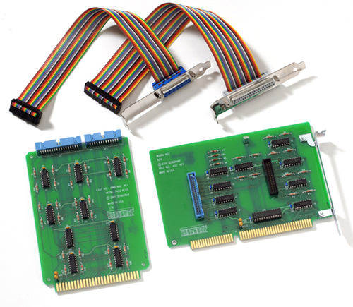
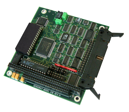
| 16:47, 29 March 2017 | 518 photo.jpg (file) |  |
246 KB | Reverted to version as of 17:48, 11 March 2016 | 3 |