Difference between revisions of "826"
(→ADC accuracy specification: +specs) |
(→ADC: +Max analog input current section) |
||
| Line 68: | Line 68: | ||
|} | |} | ||
| + | |||
| + | ===Maximum input voltage=== | ||
| + | |||
| + | The analog inputs accept common mode voltages up to ±12V with no resulting input current or damage. CMV up to ±25V is tolerated continuously, though this will cause currents to flow in the analog inputs. CMV greater than 25V may be tolerated for brief intervals, but this may cause significant currents to flow in the analog inputs and is not specified nor guaranteed to be safe. | ||
==DAC== | ==DAC== | ||
Revision as of 16:58, 2 October 2014
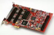
Sensoray's model 826 is a versatile analog and digital I/O system on a PCI Express board. It has 48 digital I/Os with edge detection, sixteen 16-bit analog inputs, eight 16-bit analog outputs, six 32-bit counter channels, a watchdog timer with fail-safe controller, and a flexible signal router. The board's high performance, compact size, and abundant resources make it ideally suited for a wide range of measurement and control applications.
Contents |
ADC
Calibration errors caused by missing shunt
On 826 SDKs earlier than version 3.2.0, analog calibration values will not be applied without J6 (labeled "Calibration Enable") installed. A missing shunt is intended to protect against accidental overwriting of calibration values, but in these SDKs it also prevents the reading of those values. This is resolved in SDK version 3.2.0 and above; in these versions the shunt functions as intended and must be installed only when calibrating the board (though leaving it installed all the time is okay).
If board calibration is incorrect, make sure J6 is installed or upgrade to SDK version 3.2.0 or higher. The 826 SDK can be downloaded from the 826 product page.
Apparent nonlinearity
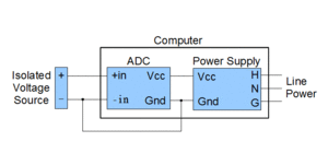
Many of our customers have observed ADC nonlinearity during development and discovered that that it was caused by excessive common-mode voltage (CMV). This often happens when the ADC is used to measure an isolated voltage source such as a battery, thermocouple, or isolated power supply. Since the source is isolated, the CMV may float up or down until it exceeds the maximum allowed CMV of the ADC's input circuitry.
If you are using an isolated source, be sure to connect one side of the source to the ADC power supply ground as shown in the diagram to the right. This will prevent high CMV that might othewise result in apparent non-linearity or calibration errors.ADC accuracy specification
Resolution and no missing codes are both 16 bits minimum.
| PARAMETER | VALUE | UNITS | ||
|---|---|---|---|---|
| MIN | TYP | MAX | ||
| Integral Nonlinearity Error | ±0.75 | ±1.5 | LSB | |
| Differential Nonlinearity Error | ±0.5 | ±1.25 | LSB | |
| Gain Error | ±2 | ±40 | LSB | |
| Gain Error Temperature Drift | ±0.3 | ppm/°C | ||
| Zero Error | ±0.8 | mV | ||
| Zero Temperature Drift | ±0.3 | ppm/°C | ||
Maximum input voltage
The analog inputs accept common mode voltages up to ±12V with no resulting input current or damage. CMV up to ±25V is tolerated continuously, though this will cause currents to flow in the analog inputs. CMV greater than 25V may be tolerated for brief intervals, but this may cause significant currents to flow in the analog inputs and is not specified nor guaranteed to be safe.
DAC
Linux Demo Sine Wave Generator counter error (-15)
The Linux sine wave generator demo may experience a timeout and exit with an error code -15 (S826_ERR_FIFOOVERFLOW). This occurs because the priority of the demo thread may be too low for the sample time. Linux is not a RTOS and the process (or interrupt) may be delayed and not complete the DAC output in the specified time.
Older version of the demo will exit when S826_ERR_FIFOOVERFLOW occurs. Later versions of the demo, however, will print an error code and continue outputting the sine wave.
In any case, if the DAC output sampling time requirements are very small and need to be precise, it is recommended to run the process at a higher priority. You may also consider using a low-latency or rt kernel.
To run the demo at a higher priority:
"nice -n 19 ./s826demo"
For Ubuntu low-latency kernel:
"sudo apt-get install linux-lowlatency linux-headers-lowlatency"
For Ubuntu rt kernel:
"sudo apt-get install linux-rt linux-headers-rt"
In extreme high performance cases, you may consider using the raw DAC write command (S826_DacRawWrite) instead of S826_DacDataWrite. You must make sure to understand the DAC ranges before doing so. This should normally not be necessary as S826_DacDataWrite is only marginally slower.
DAC accuracy specification
Resolution and monotonicity are both 16 bits minimum.
| PARAMETER | CONDITIONS | VALUE | UNITS | ||
|---|---|---|---|---|---|
| MIN | TYP | MAX | |||
| Integral Nonlinearity | ±2 | LSB | |||
| Differential Nonlinearity | ±1 | LSB | |||
| Gain Error | ±4 | ±20 | LSB | ||
| Gain Temperature Coefficient | ±2 | ppm/°C | |||
| Unipolar Zero-Scale Error | 5V unipolar range, 25°C 10V unipolar range, 25°C 5V unipolar range 10V unipolar range |
±80 ±100 ±140 ±150 |
±200 ±300 ±400 ±600 |
µV µV µV µV | |
| V_offset Temperature Coefficient | All unipolar ranges | ±2 | µV/°C | ||
| Bipolar Zero Error | All bipolar ranges | ±2 | ±12 | LSB | |
Counters
Snapshot counts upon match
When a snapshot is caused by counts equal to a compare register, the snapshot counts will always be equal to the compare register value.
Programming for incremental encoders
Which functions should I use for incremental encoders?
There are many options, but basic operation works as follows:
First configure and enable the counter channel:
Call S826_CounterModeWrite() with mode=0x00000070
Call S826_CounterStateWrite() with state=1
To read the current encoder counts:
Call S826_CounterRead()
DIOs
Generating a burst of pulses
How can I make a DIO channel go active for 10ms and then inactive for another 10ms, and repeat this five times?
There are many ways to do this but the methods you can use depend on a number of factors. Here are two general strategies:
1. If high precision is not needed you can call S826_DioOutputWrite() multiple times, with 10ms software delays between the calls. The precision of this method depends on your operating system and system load. The code for this method is simple and straightforward.
2. If you need precise timing then you could use two counter channels. For example, using counter channels 0 and 1:
- Counter 0: Configure as PWM generator with 10ms on/off times, with external enable. Connect its enable input to counter 1's output. The goal here is for counter 0 to enable counter 1 to output pulses; counter 0 will enable the PWM generator until 5 pulses have been generated.
- Counter 1: Configure as event down-counter, with preload (value=5) upon enable, with external clock, with output active when counts not zero. Connect its clock input (must be external connection) to counter 0's output. The goal here is for counter 1 to count PWM pulses until it counts from 5 down to 0; it will then set its output low, thus disabling the PWM generator.
Software Updates
1. Windows 3.3.4
- C# demo application added to SDK. Error checking for invalid modes to S826_CounterModeWrite.
2. Linux 3.3.5
- C# GUI demo available, using Linux mono. To get required libraries on Ubuntu, type:
"sudo apt-get install mono-complete"
For a C# development environment, type:
"sudo apt-get install monodevelop"

