
Multifunction analog/digital I/O | Model 826

- Six 32-bit counters support incremental encoders, PWM/pulse generation & frequency/period/pulse measurement
- 16 differential analog inputs, 16-bit, 300 ks/s
- 8 analog outputs, 16-bit, 900 ks/s
- 48 digital I/Os with edge detection
- Multistage watchdog timer with final-stage relay
- Fail-safe output controller
- Board ID switches for easy device identification
Description
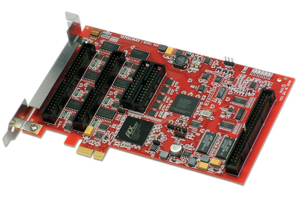
Sensoray's model 826 is a versatile analog and digital I/O system on a PCI Express board. It has 48 digital I/Os with edge detection, sixteen 16-bit analog inputs, eight 16-bit analog outputs, six 32-bit counters with quadrature decoders, a watchdog timer with fail-safe controller, and a flexible signal router. A board ID switch is provided to allow multiple 826 boards to easily coexist on a backplane. The board's high performance, compact size, and abundant resources make it ideally suited for a wide range of measurement and control applications including robotics, scientific instruments, CMM and CNC machines, control loaders, motion platforms, factory automation, and packaging and conveyor equipment.
826 block diagram
Software
Free Linux and Windows software development kits are available for model 826 (click the Downloads tab above). The SDKs include a high-level application program interface that provides thread-safe access to the board's hardware resources.
The API supports both polled and event-driven operation to facilitate any strategy of single- or multi-threaded programming. Hardware states are preserved when the API starts or terminates to allow unconflicted, concurrent access by multiple processes, and graceful, non-disruptive warm starts.
Experienced programmers will appreciate the API's use of high-performance blocking functions for event handling. These allow the API to seamlessly manage interrupts, while eliminating both the development costs and the performance penalties of asynchronous callbacks.
Pre-built API libraries are included, and the generic, open-source API is designed to reliably work with and easily port to real-time operating systems. Comprehensive documentation and source code examples in C/C++, C# and VB.NET are provided to accelerate software development, and a VI is available for Labview developers.
Connectors and cables
Low-profile headers and flat cables (not included) are used to connect I/O signals to external circuitry, enabling the board to easily fit into high-density systems while still allowing the use of popular IDC cables and connectors. The board's mounting bracket employs a built-in cable clamp to keep wires organized and secure. Sensoray offers a variety of cables and breakouts for connecting the board to field wiring; click the Accessories tab above for details.
Board mounting bracket with integrated cable clamp


Counters
Each 32-bit counter can independently perform popular functions such as incremental encoder interface, frequency counter, pulse/PWM generator, and pulse width/period measurement. The flexible architecture enables a diverse range of applications, including two-signal edge separation measurement, retriggerable and non-retriggerable one-shots, and precise, hardware-timed program delays.
Rotary and linear incremental encoders are supported by high-performance quadrature clock decoders and a versatile sampling system, allowing the board to serve as a complete six-axis motion interface. Multiple, concurrent triggers are available to accommodate applications such as periodic sampling for motion control feedback, simultaneous multi-channel sampling (e.g., for touch-trigger probes), or both at the same time.
For demanding real-time applications, every counter includes a 16-deep event FIFO that simultaneously captures timestamp and trigger information along with counts — at rates up to 50 million events per second — so that important events will never be missed. High-resolution timestamps (1 µs) ensure precise measurement of time-critical phenomena such as incremental encoder speed and position.
1 of 6 counter channels
Dedicated clock and index input pins accept both differential RS-422 and single-ended TTL signals, and the software-controlled signal router can be used to connect a counter's I/O signals to digital I/Os and other counters. Programmable filters are provided to eliminate noise and glitches from input signals.
Analog I/O
Analog inputs can be independently configured for ±1V, ±2V, ±5V, or ±10V measurement ranges. When triggered, a burst of up to sixteen samples is acquired. Conversion bursts can be software or hardware triggered, or the controller can continuously perform back-to-back bursts.
Analog input system
The eight analog outputs can be independently configured for 0 to +5V, 0 to +10V, ±5V, or ±10V output ranges. All analog circuitry employs fully electronic calibration, with factory-programmed calibration data stored on-board to allow boards to be easily and quickly installed.
Digital I/O
Each open-drain digital I/O (DIO) can operate as an input or output, or implement active low wired-OR or active high wired-AND functions. Input edge detection is supported on all channels, and input filters are available for contact debouncing and noise/glitch suppression. For maximum flexibility, the API allows any program thread to block while waiting for edge events within an arbitrary set of channels.
1 of 48 DIO channels
Standard 50-pin headers are used to connect the DIOs to Sensoray breakout boards or solid-state relay (SSR) racks, or to custom signal distribution systems. Special circuitry ensures that when the 826 is unpowered, its DIOs will not energize SSRs on externally powered racks — a hazardous behavior commonly found in other I/O boards.
Watchdog Timer
The three-stage watchdog timer can initiate a sequence of actions according to user-defined timing. Various types of actions can be triggered, including fail-safe activation, generating interrupt requests, and energizing the on-board solid state relay to invoke a system reset or signal other external circuitry.
Fail-safe Controller
The board's fail-safe controller switches analog and digital outputs to "safe" states upon receiving a trigger. The controller works in concert with the watchdog timer and external devices, such as E-stop (emergency stop) and safety interlock contacts, to automatically switch output signals to safe levels without software intervention.
Accessories
26-pin breakout board
Model 7503TDIN breaks out signals from three counter channels. It connects to the 826 with an 826C1 cable. Two 7503TDINs can be used to break out all six counter channels.
7503TDIN — DIN rail mountable, 26 conductor breakout board

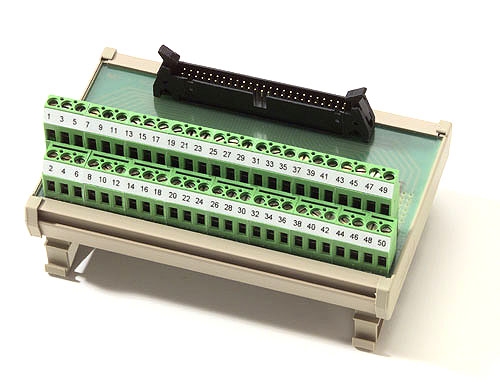
50-pin breakout board
Model 7505TDIN breaks out the 826's analog or digital I/O (DIO) signals. It connects to the 826 with an 826C2 cable. One 7505TDIN will break out all of the analog signals, or 24 of the 48 DIO signals. Three 7505TDINs can be used to break out all analog and DIO signals.
7505TDIN — DIN rail mountable, 50 conductor breakout board
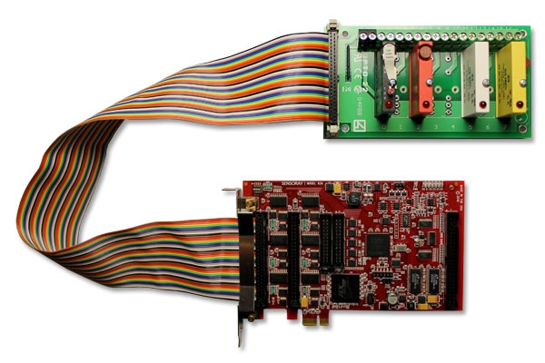
Solid-state relays
Model 7501T8 connects eight DIO signals to solid state relays (SSRs). It has sockets for any combination of type G4 SSRs (AC or DC, input or output). It connects to the 826 with an 826C2 cable.
7501T8 — panel mountable, 8 solid state relay board
Cables
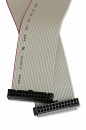
Two cables are available for connecting the 826 to external circuitry. Both have a low profile connector at one end that plugs into the 826 board. The other end has a standard IDC male connector with 0.1-inch pin spacing. Standard cable length is 24 inches; please call if you need a custom length.
- Cable type 826C1 connects up to three counter channels; two cables are needed if four or more counters are used.
- Cable type 826C2 connects either all analog signals or 24 digital I/Os; three cables are needed if all analog and digital I/Os are used.
Specifications
| GPIOs | |
|---|---|
| Channels | 48 bi-directional, open drain, TTL/5VCMOS compatible |
| Internal pull-up resistor | 10 KΩ, 5% |
| Output low-level current | 24 mA max. per channel 72 mA total max. per 6-channel DIO group |
| Output low-level voltage | 0.6 V max. @ 12 mA 0.8 V max. @ 24 mA |
| Input voltage range ¹ | 0 to +5.5 V (normal operation) -0.5 to +6.5 V (absolute max.) |
| Input high-level threshold | 2.2 V max. |
| Input low-level threshold | 0.6 V min. |
| Input hysteresis | 0.4 V min.; 1.2 V max. |
| Input leakage ¹ | 50 μA @ 5 V, max. |
| Counters | |
| Channels | 6 |
| Resolution | 32 bits |
| Time base stability | ±50 ppm |
| Count rate | 0 to 25 MHz (external clock), 1 or 50 MHz (internal clock) |
| Input clock frequency, quadrature clocks (ClkA or ClkB) | 0 to 12.5 MHz, corresponding to these count rates: x4: 0 to 50 Mcounts/s x2: 0 to 25 Mcounts/s x1: 0 to 12.5 Mcounts/s |
| Input clock frequency, mono clock | 0 to 25 MHz, corresponding to 0 to 25 Mcounts/s |
| Input signal functions | ClockA (quadratureA/mono clock), ClockB (quadratureB clock), Index |
| Input signal compatibility | RS-422 differential, TTL/5VCMOS single-ended |
| Input CMV ¹ | -0.3 to +5.5 V (-4 to +8 V absolute max.) |
| Input differential voltage range | ±5.8 V (±12 V absolute max.) |
| Input differential high-level threshold | 200 mV max. |
| Input differential low-level threshold | -200 mV min. |
| Input resistance ¹ | 12 KΩ typical; 7 KΩ min. |
| Analog Inputs | |
| Channels | 16 differential |
| Resolution | 16 bits |
| Conversion time | 3 μs |
| Settling time | 0 μs to 335 ms per sample, programmable in 1 μs steps |
| Differential input voltage ranges | ±1V, ±2V, ±5V, ±10V |
| AIN working voltage range (signal + CMV) | ±10V |
| Absolute maximum AIN voltage ¹ | -20 to +20 V continuous -30 to +30 V peak (1 ms pulses, 10% duty cycle max.) |
| CMRR | 80 dB @ 1kHz, 65 dB @ 10kHz |
| Integral nonlinearity | ±1.5 LSB maximum |
| Differential nonlinearity | ±1.25 LSB maximum |
| Gain error | ±2 LSB typical, ±40 LSB maximum |
| Zero error | ±0.8 mV maximum |
| Input impedance (either AIN to AGND) | > 10 MΩ in parallel with 100 pF |
| Analog Outputs | |
| Channels | 8 single ended, with local (on-board) sensing |
| Resolution | 16 bits |
| Output ranges | 0 to +5V, 0 to +10V, ±5V, ±10V |
| Conversion time | 1.04 μs |
| Output current | ±2 mA maximum |
| Integral nonlinearity | ±2 LSB maximum |
| Differential nonlinearity | ±1 LSB maximum |
| Gain error | ±4 LSB typical; ±20 LSB maximum |
| Unipolar zero error | 5V range, 25°C: ±80 μV typical, ±200 μV maximum 10V range, 25°C: ±100 μV typical, ±300 μV maximum 5V range: ±140 μV typical, ±400 μV maximum 10V range: ±150 μV typical, ±600 μV maximum |
| Bipolar zero error | ±2 LSB typical; ±12 LSB maximum |
| Watchdog and Fail-safe | |
| Timer stages | 3 |
| Interval (per stage) | Programmable from 20 ns to 85.9 s, in 20 ns steps |
| Output events | Stage 0: Fail-safe trigger, IRQ Stage 1: NMI out via digital output, PCIe Fatal Error Stage 2: Reset via digital output or onboard solid state relay (SSR) |
| Fail-safe control | Independent enable and state for each of 48 digital I/Os, 8 analog outputs |
| Host Interface | |
| System bus | PCI Express, x1, compliant to PCIe Specification 1.0a |
| Dimensions | PCI Express standard height, half-length
|
| Power | |
| Input power (nominal, w/no external loads) | +12 V @ 350 mA, +3.3 V @ 450 mA |
| +5V out | 5VDC ±5%, 400 mA max. (total for all DIO/counter connectors) |
| Environmental | |
| Operating temperature | 0 to 70°C |
| Storage temperature | -40 to 70°C |
| Pressure, operating | 650 to 1010 hPa |
| Humidity, operating | 20% to 80% RH, non-condensing |
Notes
1: Applicable when 826 board is powered or unpowered.
Documentation
| File | Version | Date M-D-Y | Type | Size |
|---|---|---|---|---|
| Manuals | ||||
| Model 826 technical manual Hardware and API documentation | 3.0.10 | 03-18-26 | 894 KB | |
| Quick start guide for Windows | — | 03-18-26 | 56 KB | |
| Online user guide for Windows demo | — | — | HTML | — |
| Mechanical | ||||
| 3D model | — | 03-18-26 | STEP | 4.37 MB |
| Application Notes | ||||
| Model 826 tech support wiki FAQs, examples and additional information | — | — | HTML | — |
| Solid-state relay racks, models 7501T8 / 7501T16 / 7501T24 | — | — | HTML | — |
| Open-source I²C emulator How to control an I²C bus with model 826 | — | 03-18-26 | 115 KB | |
| Single and multistage watchdog timers Introduction to watchdog timers: their architecture, function and application | 1.0.0 | 03-18-26 | 296 KB | |
| Other | ||||
| Statement of volatility Memory attributes, for security and material-handling professionals | — | 03-18-26 | 97 KB | |
| CE compliance report | — | 03-18-26 | 3.86 MB | |
| REACH certificate of compliance | — | 03-18-26 | 101 KB | |
Downloads
| File | Version | Date M-D-Y | Type | Size |
|---|---|---|---|---|
| Windows software development kit Compatible with Windows 11, 10, 8, 7 and XP | 3.4.11 | 03-01-26 | ZIP | 61.15 MB |
| Linux software development kit | 3.3.17 | 03-18-26 | BZ2 | 629 KB |
| Matlab API wrapper and demo | 1.0.1 | 03-18-26 | ZIP | 9 KB |
| LabVIEW instrument driver | 1.0.0 | 03-18-26 | ZIP | 1.13 MB |
| Other Operating Systems | ||||
| Need a software development kit for another operating system? We can port our SDK to your OS for a NRE fee or, with a volume commitment, at no additional cost. Contact Sales for details. | ||||