
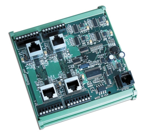
4-channel RTD/Load Cell Interface Module | Model 2612
- Interfaces 4 load cells / RTDs to Ethernet
- Simultaneous measurement of four sensors
- 6- or 4-wire connections for high precision
- 200 nV resolution at 6 samples/s
- Directly connects to field wiring
- Connects to Ethernet through 2601
- DIN-3 rail mountable
Description
Model 2612 is a modular, four-channel resistive sensor interface that connects to Ethernet through a model 2601 communication module. It has four sensor input channels that can measure any combination of strain/pressure gauges, RTDs, and other passive resistive sensors with 24-bit accuracy. The module is a member of the 2600 series of smart I/O modules.
Analog Inputs
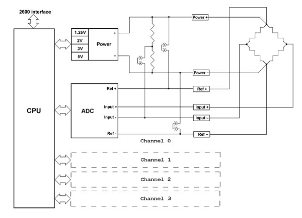
All measurements are made differentially to reduce common mode noise. Each channel has bridge excitation outputs with remote voltage sensing, enabling 6-wire measurements for the highest possible accuracy. RTD temperature sensors with alphas of 385 or 392 are supported, as well as other resistive devices, by integrating them into full bridge circuits. External bridge completion resistors can be easily added to the module's terminal block. Field wiring is connected directly to the 2612 via removable terminal blocks — no external termination systems are needed.
2612 block diagram, with strain gauge shown connected to one channel
Calibration
The 2612 maintains high accuracy by periodically sampling on-board references and using the acquired samples to correct subsequent sensor measurements. Factory calibration constants are stored in non-volatile memory so that 2612 modules can be easily installed and replaced.
Modular System
The 2612 can be connected to any of the sixteen IOM (I/O module) ports on the 2601 with a low-cost category-5 patch cable, which conveys all required operating power and communication signals. All inter-module communication circuits are optically isolated to prevent potentially disruptive ground loops.
| Use the Design Assistant to quickly design a system and calculate pricing. |

Specifications
| Analog Inputs | |
|---|---|
| Resolution | 24 bits |
| Input channels | 4 |
| Conversion rate | 6.875 to 3500 samples/second for each channel |
| Input range | ±1/2 of reference |
| Input impedance | 110 kΩ |
| Power Outputs | |
| Output channels | 4 |
| Output power | 1.25 V, 2 V, 3 V or 5 V, ±10% at 1 to 25 mA for each channel. |
| Mating Connectors | |
| IOM port (qty 1) | RJ-45 plug, AMP 554169 or equivalent |
| Analog inputs (qty 4) | RJ-45 plug, AMP 554169 or equivalent
Pluggable TB, 8-pin, RIA 31166108 or equivalent (included with module) |
| Temperature | |
| Operating range | 0 to 70 °C |
| Power | |
| Input power | ±24 V, ±5% at 60 mA. |
| Mechanical | |
| Outer dimensions | 5.0H x 5.0W x 1.8D inches, including DIN mounting frame. Depth is specified with respect to surface of DIN rail support panel. Additional clearance required for field wiring. |
Documentation
| File | Version | Date M-D-Y | Type | Size |
|---|---|---|---|---|
| Manuals | ||||
| 2600 Hardware Manual | 2.0.2 | 10-17-24 | 489 KB | |
| 2600 Programming Guide | 1.12.0 | 10-17-24 | 232 KB | |
| Application Notes | ||||
| Tech support wiki for 2600 family | — | — | HTML | — |
Downloads
| File | Version | Date M-D-Y | Type | Size |
|---|---|---|---|---|
| 2600 Software Development Kit For Linux and Windows | 1.1.18 | 10-17-24 | ZIP | 2.04 MB |
| 2600 Labview Drivers | 1.0.0 | 10-17-24 | ZIP | 542 KB |
| Other Operating Systems | ||||
| Need a software development kit for another operating system? We can port our SDK to your OS for a NRE fee or, with a volume commitment, at no additional cost. Contact Sales for details. | ||||
Pricing & Ordering
| Use the Design Assistant to quickly design a system and calculate pricing. |