
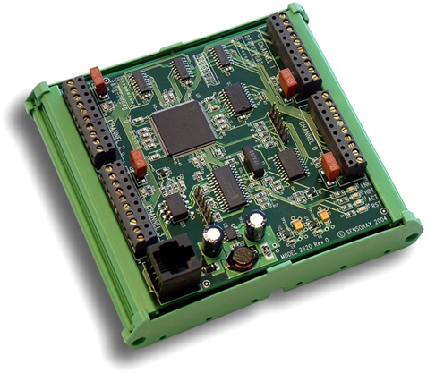
4-channel Counter/Incremental Encoder Interface Module | Model 2620

- Interfaces 4 advanced 32-bit counters to Ethernet
- Quadrature decoders for incremental encoders
- Removable terminal blocks for direct field wiring
- Supplies 5V power for encoders
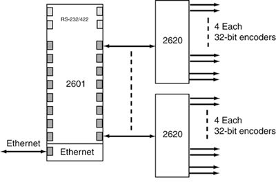
- Connects to Ethernet through 2601
- DIN-3 rail mountable
Description
Model 2620 is a modular, four-channel counter/timer interface that connects to Ethernet through a 2601 communication module. It has four advanced 32-bit counter channels that can directly interface to incremental encoders as well as single-clock sources. Network latency is mitigated by providing timestamps along with all counter values read by the host computer. Model 2620 is a member of the 2600 series of smart I/O modules.
Several 2620s can be connected to a single 2601
Field Wiring
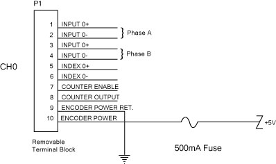
Four inputs are provided on each channel: enable, index, and two clocks. The clock and index inputs accept both differential RS-422 and single-ended TTL/CMOS compatible signals. Each channel has one output signal that can be used for PWM or pulse generation.
All field wiring is connected directly to the 2620 via removable terminal blocks, which are supplied with the module. These eliminate the need for external terminal blocks and make module installation and removal a snap.
Pinout of removable terminal block
Applications
Each counter channel can be independently configured to implement any of these popular functions:
- Incremental encoder interface. The quadrature clock decoders have programmable x2/x4 clock multipliers that increase counting resolution for quadrature encoders. A counter can be forced to a preset value in response to a trigger signal on the index input or through software.
- PWM generator. Any channel can be configured to produce a periodic output with a programmable period and duty cycle.
- Pulse generator. An output pulse can be generated in response to a hardware or software trigger. The pulse duration is determined by a value in the preload register.
- Frequency measurement. An internal time gate generator is provided for frequency measurement applications. Frequency can be measured by using the internal gate generator or an external gate signal.
- Pulse width measurement. The width of a digital pulse can be measured when connected to the index input.
- Period measurement. The period of a digital signal can be measured by connecting it to the index input.
Modular System
A 2620 module can be connected to any of the sixteen IOM (I/O module) ports on the 2601 with a low-cost category-5 patch cable, which provides all operating power and communication signals needed by the 2620. All inter-module communication circuits are optically isolated to prevent potentially disruptive ground loops.
| Use the Design Assistant to quickly design a system and calculate pricing. |

Specifications
| Counters | |
|---|---|
| Resolution | 32 bits |
| Counter channels | 4 |
| Count rate | 10 MHz, maximum |
| Input clock frequency maximums | 2.5 MHz (quadrature x4)
5 MHz (quadrature/mono x2) 10 MHZ (quadrature/mono x1) Derate for deviations from 50% duty cycle |
| Internal clock | 10 MHz |
| Mode of Operation Measurement Ranges | |
| Incremental encoder | 0 to 10 MHz |
| Pulse generator | 100 ns to 214 s |
| PWM generator | 100 ns to 214 s |
| Single pulse width measurement | 100 ns to 214 s |
| Period measurement | Up to 10 MHz |
| Freqency measurement | Up to 10 MHz |
| Input/Output Signals | |
| Clock input | RS-422 differential
TTL/5VCMOS compatible ±7V CMV maximum |
| Index input | RS-422 differential
TTL/5VCMOS compatible ±7V CMV maximum |
| Count enable input | TTL/5VCMOS compatible |
| Counter output | TTL/5VCMOS compatible |
| Device Power Outputs | |
| Output voltage | 5VDC, ±5% |
| Output current | 400mA maximum, total for all channels |
| Fuse | socketed 500mA fuse per channel |
| Mating Connectors | |
| IOM port (qty 1) | RJ-45 plug, AMP 554169 or equivalent |
| Counter I/O (qty 4) | Pluggable TB, 10-pin, RIA 31166110 or equivalent
(included with module) |
| Temperature | |
| Operating range | 0 to 70 °C |
| Power | |
| Input power
(not including external device power) |
+24V, ±5% (at 30mA) |
| Dimensions | |
| Outer dimensions | (W x H x D): 4.1 x 5.0 x 2.0 inches, including DIN mounting frame
Depth is specified with respect to surface of DIN rail support panel Additional clearance required for field wiring |
Documentation
| File | Version | Date M-D-Y | Type | Size |
|---|---|---|---|---|
| Manuals | ||||
| 2600 Hardware Manual | 2.0.2 | 10-17-24 | 489 KB | |
| 2600 Programming Guide | 1.12.0 | 10-17-24 | 232 KB | |
| Application Notes | ||||
| Tech support wiki for 2600 family | — | — | HTML | — |
| Mechanical Drawings | ||||
| Module Dimensions and Layout | 1.0.0 | 10-17-24 | 146 KB | |
| CE Reports | ||||
| CE Test Report | — | 10-17-24 | 817 KB | |
Downloads
| File | Version | Date M-D-Y | Type | Size |
|---|---|---|---|---|
| 2600 Software Development Kit For Linux and Windows | 1.1.18 | 10-17-24 | ZIP | 2.04 MB |
| 2600 Labview Drivers | 1.0.0 | 10-17-24 | ZIP | 542 KB |
| Other Operating Systems | ||||
| Need a software development kit for another operating system? We can port our SDK to your OS for a NRE fee or, with a volume commitment, at no additional cost. Contact Sales for details. | ||||
Pricing & Ordering
| Use the Design Assistant to quickly design a system and calculate pricing. |