
8/16-channel Solid State Relay I/O Module | Model 2652/2653

- Supports 8 (Model 2652) or 16 (Model 2653) standard SSRs
- Input SSRs are debounced
- PWM mode for output SSRs
- Integrated support for interlock circuits
- Finger-safe field wiring connectors
- Connects to Ethernet through 2601
- DIN-3 rail mountable
Description
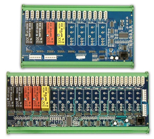
Models 2652 and 2653 are DIN rail mountable modules that allow solid state relays (SSRs) to be monitored and controlled over Ethernet. Sockets are provided for eight (model 2652) or sixteen (model 2653) SSRs. Each socket may be populated with any supported SSR type, including AC in, AC out, DC in and DC out, or left unpopulated. SSRs are secured to the module with integral hold-down screws. The modules, which work in conjunction with a model 2601 communication module, are members of the 2600 series of smart I/O modules.
Simple system with up to 16 SSRs
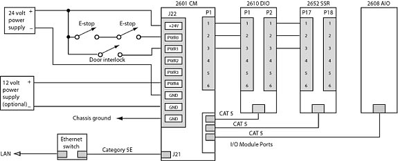
The 2652 and 2653 modules communicate with a 2601 communication module through an optically isolated interface, thereby eliminating problematic ground loops and ensuring error-free operation in demanding industrial environments. Two cables connect the 2652/2653 to the 2601: a standard Category-5 UTP patch cable for inter-module communication, and a six-conductor power cable that supplies control power for the SSRs through an integral safety interlock system.
The 2600 family is well-suited for applications that have high I/O counts. As many as sixteen I/O modules can be connected to a 2601, in any combination of I/O module types. This enables up to 256 solid state relays to be controlled from a single Ethernet port, by connecting one 2601 module to 16 2653 modules.
More complex system with up to 256 SSRs
Field wiring
The modules provide built-in, finger-safe connectors for all high voltage signals. Two-piece mating connectors are supplied to allow field wiring to be directly connected to the module — no external termination boards are needed. Two connectors are provided for each SSR, one for the line (power source) connection and one for the load. This organization greatly simplifies the field wiring and enables electric loads to be easily connected and disconnected for quick servicing.
PWM output
Each output SSR may be explicitly controlled by the Ethernet client or it may operate as a PWM (pulse width modulated) output, with rate and duty cycle specified by the client. This feature simplifies the closed-loop control of devices such as electric heaters by removing the time-critical burden of PWM generation from the network and host computer.
Interlocks
Models 2652 and 2653 include five interlock circuits. Each interlock circuit conveys a signal that may be interrupted by external safety interlock switches, emergency stop switches, or other similar contacts. Each output SSR can be shunt-configured to be enabled by any one of the five interlock signals. An output SSR will unconditionally de-energize when its interlock signal is interrupted, thus ensuring fail-safe deactivation when safety conditions require it.
Two connectors are provided for the interlock circuits. One of these connects to the interlock signal sources (typically power supply outputs). If needed, the other connector can be used to pass through the interlock voltages to other modules such as a 2610 digital I/O module or additional 2652/2653 modules. This "daisy-chain" system eliminates the external termination boards that are often required for interlock circuits.
Model 2652/2653 Interlock
Mechanical
Series 2600 modules utilize robust, uniform 100-mm-wide DIN rail mountable frames that enable the modules to be quickly attached to and detached from standard 35-mm-wide DIN rails. This lowers installation costs because DIN rails, unlike panel-mounted products, do not require precise mounting hole positions or time-consuming assembly.
All modules in the 2600 family employ open-frame design, with field wiring connectors conveniently located at module edges for easy cable routing into adjacent wiring ducts. This eliminates the expensive module enclosures that are found in many competing products.
Modular System
The 2652/2653 can be connected to any of the sixteen IOM (I/O module) ports on the 2601 with a low-cost category-5 patch cable, which conveys all required operating power and communication signals. All inter-module communication circuits are optically isolated to prevent potentially disruptive ground loops.
| Use the Design Assistant to quickly design a system and calculate pricing. |

Specifications
| Solid State Relays | |
|---|---|
| Sockets | Model 2652: 8 Model 2653: 16 |
| Type | Grayhill 70-series (24 V logic) or equivalent (not included) |
| Power and Environmental | |
| Operating temperature | 0 to 70 °C |
| Input power | +24 V, ±5% (at 310 mA), with eight energized 70-OAC24 SSRs (not included) |
| Mechanical | |
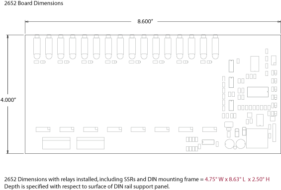
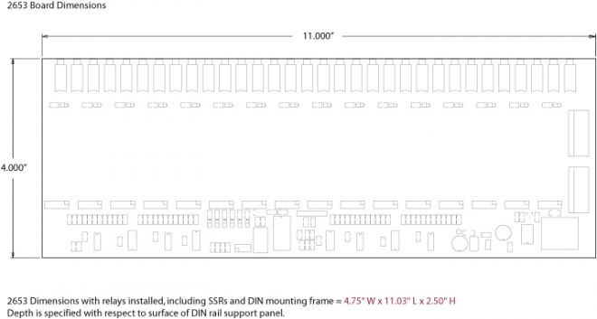
| Dimensions | see below |
| DIN rail width | 35 mm |
Documentation
| File | Version | Date M-D-Y | Type | Size |
|---|---|---|---|---|
| Manuals | ||||
| 2600 Hardware Manual | 2.0.2 | 10-17-24 | 489 KB | |
| 2600 Programming Guide | 1.12.0 | 10-17-24 | 232 KB | |
| Mechanical | ||||
| 3D model, 2653 | — | 10-17-24 | STEP | 3.1 MB |
| Application Notes | ||||
| Tech support wiki for 2600 family | — | — | HTML | — |
| Compliance | ||||
| Model 2652 CE Certification Report | — | 10-17-24 | 817 KB | |
Downloads
| File | Version | Date M-D-Y | Type | Size |
|---|---|---|---|---|
| 2600 Software Development Kit For Linux and Windows | 1.1.18 | 10-17-24 | ZIP | 2.04 MB |
| 2600 Labview Drivers | 1.0.0 | 10-17-24 | ZIP | 542 KB |
| Other Operating Systems | ||||
| Need a software development kit for another operating system? We can port our SDK to your OS for a NRE fee or, with a volume commitment, at no additional cost. Contact Sales for details. | ||||
Pricing & Ordering
| Use the Design Assistant to quickly design a system and calculate pricing. |