
Multifunction analog/digital I/O | Model 626
- Six versatile 24-bit counters support incremental encoders
- 48 bi-directional digital I/O -- 40 with edge detection
- Four 14-bit analog outputs, 20 KHz update rate
- Sixteen 16-bit differential analog inputs, 15 KHz rate
- Watchdog timer with mechanical relay output
- Battery backup of counters
Model 626 is a legacy product and is not recommended for new designs. Some of legacy products may be available but may have significant lead times and minimum order requirements. We recommend model 826 as a substitute for this product.
Description
IMPORTANT! On 626 Revision R digital I/O connectors are swapped relative to previous revisions. Please swap the cables coming into J7 and J8 if DIO is used.
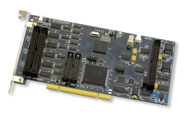
Model 626 is a PCI board that saves space and reduces cost by combining several popular interface functions on a half-size card. It has six versatile 24-bit counters that support incremental encoders as well as single-clock sources, 48 bidirectional digital I/Os (40 with edge detection), sixteen differential analog inputs, four analog outputs, and a watchdog timer. Five low profile connectors are used with optional flat cables to connect the board to external breakout boards.
Typical application
Encoders and Counters
Three 24-bit up/down counter pairs may be configured for six incremental encoders, each having 24-bits of resolution. Each channel accepts two phased TTL or RS-422 signals plus an index signal to track encoder direction and displacement. Each input is conditioned and synchronized to the 626’s internal clock.
Unlike conventional counters, the 626’s counters do not accumulate errors when the encoder dithers or changes direction. The 626 supplies 5 volt power to each encoder channel. All counters are programmable and may optionally generate interrupts.
The counter channels have a battery backup feature that keeps them running during a power failure. The 626’s battery charger will recharge an external 3.6V NiCd when power is restored.
Each counter can function as a timer using the board's internal clock or an external clock. When paired, 48-bit counters may be used for frequency measurement.
Analog Inputs
Sixteen differential input channels are multiplexed to a sample/hold and successive approximation A/D. Each channel may be programmed for ± 5V or ± 10V. No trim adjustments are needed.
Analog Outputs
Four voltage outputs may be programmed for ± 10 volts. A unique circuit prevents unpredictable D/A outputs during CPU initialization. All outputs are reset to zero volts whenever a bus reset occurs.
Watchdog Timer
The board's watchdog timer may be connected to the bus reset via a 2-pin connector. It may be enabled or disabled under program control. The timer is automatically disabled whenever a bus reset occurs. A mechanical relay is provided to signal external circuitry. The relay can be activated by the watchdog timer or under software control.
Fail-safe Digital I/O
In the event that power is lost to the PC, solid state relays connected to the 626’s digital I/O will not be powered to the on state. This allows solid state relay boards to be powered from a remote power supply without the chance of output relays turning on when the PC is turned off.
Digital I/O
The board's 48 digital lines have standard pinouts for solid state relay boards. Each line is software programmable as an input or output. 40 of the inputs may be independently programmed for edge detection. All outputs are turned off upon system reset.
Accessories
26-pin breakout board
Model 7503TDIN breaks out signals from three counter channels. It connects to the 626 with an 7503C/7503C1 cables. Two 7503TDINs can be used to break out all six counter channels.
7503TDIN — DIN rail mountable, 26 conductor breakout board

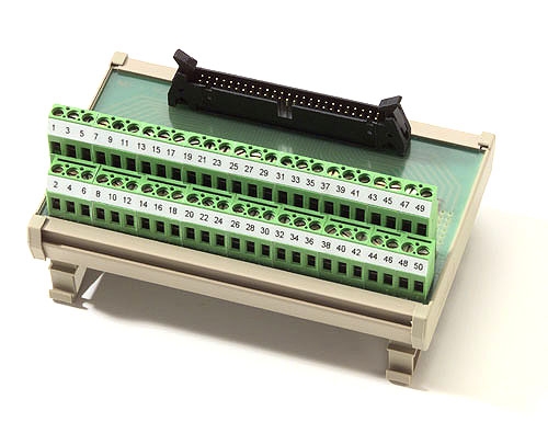
50-pin breakout board
Model 7505TDIN breaks out the 626's analog or digital I/O (DIO) signals. It connects to the 626 with an 7501C/7501C1 cables. One 7505TDIN will break out all of the analog signals, or 24 of the 48 DIO signals. Three 7505TDINs can be used to break out all analog and DIO signals.
7505TDIN — DIN rail mountable, 50 conductor breakout board
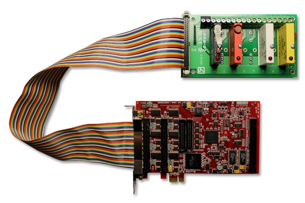
Solid-state relays
Model 7501T8 connects eight DIO signals to solid state relays (SSRs). It has sockets for any combination of type G4 SSRs (AC or DC, input or output). It connects to the 626 with an 7501C or 7501C1 cable.
7501T8 — panel mountable, 8 solid state relay board
Cables
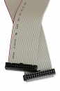
Two cables are available for connecting the 626 to external circuitry. Both have a low profile connector at one end that plugs into the 626 board. The other end has a standard IDC male connector with 0.1-inch pin spacing. Standard cable length is 24 inches; please call if you need a custom length.
- Cable type 7503C/7503C1 connects up to three counter channels; two cables are needed if four or more counters are used.
- Cable type 7501C/7501C1 connects either all analog signals or 24 digital I/Os; three cables are needed if all analog and digital I/Os are used.
Specifications
| Analog Inputs | |
|---|---|
| Number of channels | 16 differential |
| Conversion time | 20 µs/channel |
| Input resistance | 100 MΩ |
| CMRR | 100 dB minimum |
| Maximum common mode voltage | ±5 V |
| Resolution | 16-bits |
| Accuracy | 14-bits |
| Input ranges | ±10 V, ±5 V |
| Offset error | ±1/2 LSB |
| Analog Outputs | |
| Channels | 4 |
| Conversion time | 200 µs/channel |
| Resolution | 14 bits |
| Offset error | ±2 bits |
| Output voltage | ±10 V |
| Output resistance | 87 Ω |
| Digital I/O | |
| Number of channels | 48 bi-directional |
| Output voltage | 0 to 5 V open collector |
| Output sink current | 100 mA (at 1.1 V) |
| Connector | 50 pin, low profile, for flat cable |
| Counters | |
| Channels | 6, 24 bits, quadrature-encoded or single-clock |
| Input signals | TTL or RS-422 |
| Input frequency | 2 MHz with internal clock
1 MHz with external clock |
| Quadrature multiplier | x1, x2, x4 |
| Battery backup | NiCd, 3.6 V |
| Connector | 26 pin, low profile, for flat cable |
| Watchdog Timer | |
| Watchdog Timer Time-out | 1/8, 1/4, 1, 10 sec |
| Environmental | |
| Bus interface | PCI, 32-bit, 33 MHz 3.3V/5 V universal bus signaling |
| Board dimensions | 4.2 x 7.0 in (107 x 178 mm) |
| Input power | < 3 W |
| Operating temperature | 0 to 70 °C |
Documentation
| File | Version | Date M-D-Y | Type | Size |
|---|---|---|---|---|
| Manuals | ||||
| Model 626 Hardware Manual | 1.0.5 | 03-18-26 | 335 KB | |
| Model 626 Software Manual | 1.0.0 | 03-18-26 | 238 KB | |
| Application Notes | ||||
| Model 626 tech support wiki FAQs, examples and additional information | — | — | HTML | — |
| Application porting guide Tools and info for migrating designs from 626 to model 826 | — | — | HTML | — |
| Images and Mechanical Drawings | ||||
| Dimensional Drawing | 1.0.0 | 03-18-26 | 33 KB | |
Downloads
| File | Version | Date M-D-Y | Type | Size |
|---|---|---|---|---|
| Model 626 Linux Software Development Kit | 1.0.5 | 03-18-26 | GZ | 183 KB |
| Model 626 Windows Software Development Kit Compatible with Windows XP, 7, 8 and 10 | 1.0.5 | 03-18-26 | ZIP | 14.46 MB |
| Other Operating Systems | ||||
| Need a software development kit for another operating system? We can port our SDK to your OS for a NRE fee or, with a volume commitment, at no additional cost. Contact Sales for details. | ||||