| Controlling Solid State Relays over Ethernet | |
|---|---|
| Control systems have historically relied on a hodgepodge of competing and, in many cases, incompatible field buses. In addition to their proprietary protocols and high costs, these buses suffer from a plethora of cabling complications, termination schemes, and obsolescense. Fortunately, there is now a superior alternative: Ethernet. |

|
|
Ethernet is winning its way into ever-higher percentages of control systems for some very good reasons:
Ethernet is winning based on technical merits as well; its built-in electrical isolation eliminates the ground loops that commonly plague other field buses, and its data rates greatly surpass those of older field buses. Ethernet is the field bus of choice for modern designs. All Things ConsideredMany control systems employ solid state relays (SSR) to control devices such as motors, solenoids and lights. It should come as no surprise, then, that the ability to control these relays via Ethernet is highly desirable. Not so obvious, however, is the fact that there is much more to this than just turning relays on and off. System designers must consider a number of critical issues when relays will be controlled over an Ethernet: Versatility: Ideally, a relay rack will accommodate industry standard relays such as the 0AC24. This will ensure the high availability of low cost relays from multiple sources. The rack should provide a socket for each SSR so that different relay "flavors" (e.g., AC/DC, input/output types) can be installed on the rack as needed. Although higher densities can be achieved with multi-channel SSRs, there is a price to be paid for this in the form of reduced versatility and smaller load currents. Flexibility: Many relay racks support only a single control supply voltage, typically 5 volts DC. Machine control applications, on the other hand, often employ devices which have varied supply voltage requirements (e.g., 5VDC, 12VDC, 24VDC). This disparity forces the system designer to compromise by using sub-optimal devices or by providing a separate relay rack for each supply voltage (expensive!). A truly flexible relay rack will support multiple relay control voltages. Diagnostics: Ethernet-based relay racks are complex, intelligent devices that include a CPU and communication interface. This complexity must not be allowed to burden field service personnel. Field service technicians must be able to tell at a glance whether a rack is working. If a rack is functioning normally it should give an appropriate visual indication. Similarly, a rack should indicate the presence of a malfunction and, ideally, it will indicate the nature of the problem as well. A visual indicator should be provided for each relay so that technicians can easily determine relay states. Fail-safe Operation: Relays often control devices that must be turned off in a fail-safe manner for safety reasons (i.e., to prevent injuries to people or equipment). When such a requirement arises, the relay must turn off, even if the relay rack has malfunctioned. In order to accomplish this, the relay rack must work in harmony with interlock and/or emergency stop contacts. These contacts, which supply the activation current to specific combinations of relays, will deactivate the relays when opened. Unless the relay rack has built-in support for interlock contacts, it will be both difficult and expensive to implement fail-safe operation. Embeddability: "Dumb" relay racks must be located near their controllers because of cable length limitations. Smart relay racks, on the other hand, are not subject to this limitation. Smart relay racks can be located quite far away from their controllers and thus can often be found deeply embedded in their host systems. Deeply embedded electronic devices must always recover to a known, safe state when a fault occurs or upon loss of communication with the controller (due to unexpected controller shutdown or communication failure). Smart relay racks should always include a "watchdog" timer to protect against fault conditions, and a communication timer to detect communication loss. Serviceability: System reconfiguration should not be necessary when a relay rack is replaced. In addition, look for other features that will simplify and speed up installation and serviceability. For example, all field wiring connections to the rack should be implemented with quick-change connectors that require no tools. Also, consider how the relay rack is mounted to its host system. DIN rail mountable relay racks can be installed or removed from an equipment cabinet in seconds; a feature that is appreciated by both system assemblers and field service personnel. |
|
| Sensoray Solutions | |
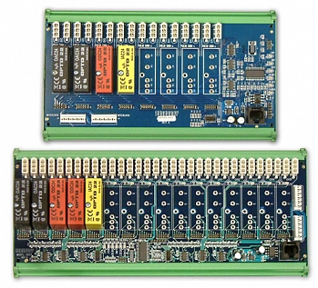
Comprehensive CoverageSensoray's model 2652 and 2653 I/O modules (8/16 SSR channels, respectively) include all of the features listed above. These modules can be used with other 2600 Family I/O modules to implement a robust, low-cost Ethernet-based measurement and control system that supports:
Models 2652 and 2653, ideal for high capacity Ethernet I/O systems
|
|
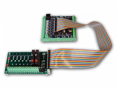
Compact FootprintIn systems that don't require built-in interlock support, Sensoray's model 2410 offers a compact, low-cost solution for controlling standard solid state relay racks over Ethernet. Controlling a simple SSR rack via Ethernet with a Sensoray model 2410
|
|