
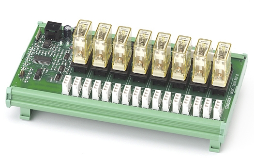
8-channel Relay Module with RH1B-U Relays | Model 2650

- Interfaces 8 mechanical relays to Ethernet
- Includes eight RH1B-U Relays and hold-down clips
- Integrated support for interlock circuits
- Finger-safe field wiring connectors
- Connects to Ethernet through 2601
- DIN rail mountable
Model 2650 is obsolete. This archived information is provided as a courtesy to customers who own model 2650 units.
Description
Model 2650 is a DIN rail mountable module that allows up to eight mechanical relays to be controlled over Ethernet. Eight socketed, RH1B-U mechanical relays are included with the module. Each of the eight sockets may be populated with a relay or left unpopulated. When populated, a socket accepts a hold-down clip (included) to secure its relay in place. It is a member of the 2600 series of smart I/O modules.
The module connects to Ethernet and obtains operating power via a model 2601 communication module. The 2650 communicates with a 2601 communication module through an optically isolated interface, thereby eliminating problematic ground loops and ensuring error-free operation in demanding industrial environments. This is done with a low-cost category-5 patch cable, which supplies communication signals and logic operating power to the 2650. A 2600C1 daisy-chain power cable is also required, to supply I/O power and route interlock signals to the module.
The 2600 family is well-suited for applications that have high I/O counts. As many as sixteen I/O modules can be connected to a 2601, in any combination of I/O module types. This enables, for example, up to 128 mechanical relays to be controlled from a single Ethernet port.
Field wiring
The module provides built-in, finger-safe connectors for all high voltage signals. Two-piece mating connectors are supplied to allow field wiring to be directly connected to the module — no external termination boards are needed. Two connectors are provided for each relay, one for the line (power source) connection and one for the load. This organization greatly simplifies the field wiring and allows electric loads to be easily connected and disconnected for quick servicing.
Interlocks
Five interlock circuits are implemented on the 2650. Each interlock circuit can convey a signal that may be interrupted by external safety interlock switches, emergency stop switches, or other contacts. Each relay can be shunt-configured to be enabled by any one of the five interlock signals. A relay will unconditionally de-energize when its interlock signal is interrupted, thus ensuring fail-safe deactivation when safety conditions require it.
A shunt selects each channel's I/O power source
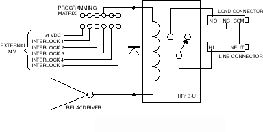
Two connectors are provided for the interlock circuits. One of these connects to the interlock signal sources (typically power supply outputs). If needed, the other connector can be used to pass through the interlock voltages to another 2650 module or other type of module such as a 2610 digital I/O module or 2652/2653 solid state relay module. This "daisy-chain" system eliminates the external termination boards that are often required for interlock circuits.
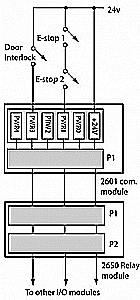
Interlock example
Mechanical
Series 2600 modules utilize robust, uniform 100-mm-wide DIN rail mountable frames that allow them to be quickly attached to standard 35-mm-wide DIN rails. This lowers installation costs because DIN rails, unlike panel-mounted products, do not require numerous, precise mounting hole positions or time-consuming assembly.
All modules in the 2600 family employ open-frame design, with field wiring connectors conveniently located at module edges for easy cable routing into adjacent wiring ducts. This eliminates the expensive module enclosures that are found in many competing products.
Modular System
A 2650 module can be connected to any of the sixteen IOM (I/O module) ports on the 2601 with a low-cost category-5 patch cable, which conveys all logic operating power and communication signals. All inter-module communication circuits are optically isolated to prevent potentially disruptive ground loops.
| Use the Design Assistant to quickly design a system and calculate pricing. |

Specifications
| Relays | |
|---|---|
| Included with module | 8, with hold-down clips |
| Type | RH1B-U |
| Contact rating | 7 A, 240 VAC
7.5 A, 120 VAC 7 A, 30 VDC |
| Coil power | 24 VDC, 30 mA |
| Power | |
| Supply voltage | 24 VDC (via optional 2600C1 cable) |
| Operating current | 310 mA with all relays powered |
| Mechanical | |
| DIN rail width | 35 mm |
| Module dimensions | (W x H x D): 8.75 x 4.84 x 1.85 inches |
| Field Wiring Connectors | |
| Type | AMP 770170 |
| Crimp pins | AMP 770988-1 |
Documentation
| File | Version | Date M-D-Y | Type | Size |
|---|---|---|---|---|
| Manuals | ||||
| 2600 Hardware Manual | 2.0.2 | 10-17-24 | 489 KB | |
| 2600 Programming Guide | 1.12.0 | 10-17-24 | 232 KB | |
| Application Notes | ||||
| Tech support wiki for 2600 family | — | — | HTML | — |
| Mechanical Drawings | ||||
| Model 2650 Dimensions | 1.0.0 | 10-17-24 | 32 KB | |
Downloads
| File | Version | Date M-D-Y | Type | Size |
|---|---|---|---|---|
| 2600 Software Development Kit For Linux and Windows | 1.1.18 | 10-17-24 | ZIP | 2.04 MB |
| 2600 Labview Drivers | 1.0.0 | 10-17-24 | ZIP | 542 KB |
| Other Operating Systems | ||||
| Need a software development kit for another operating system? We can port our SDK to your OS for a NRE fee or, with a volume commitment, at no additional cost. Contact Sales for details. | ||||
Pricing & Ordering
| Use the Design Assistant to quickly design a system and calculate pricing. |